
2 Hardware Overview
This chapter describes the Core robot’s major hardware components — the arm, the control box, and the operating-environment requirements they expect. Use it to orient yourself before installation and as a reference for specifications during integration.
2.1 Arm
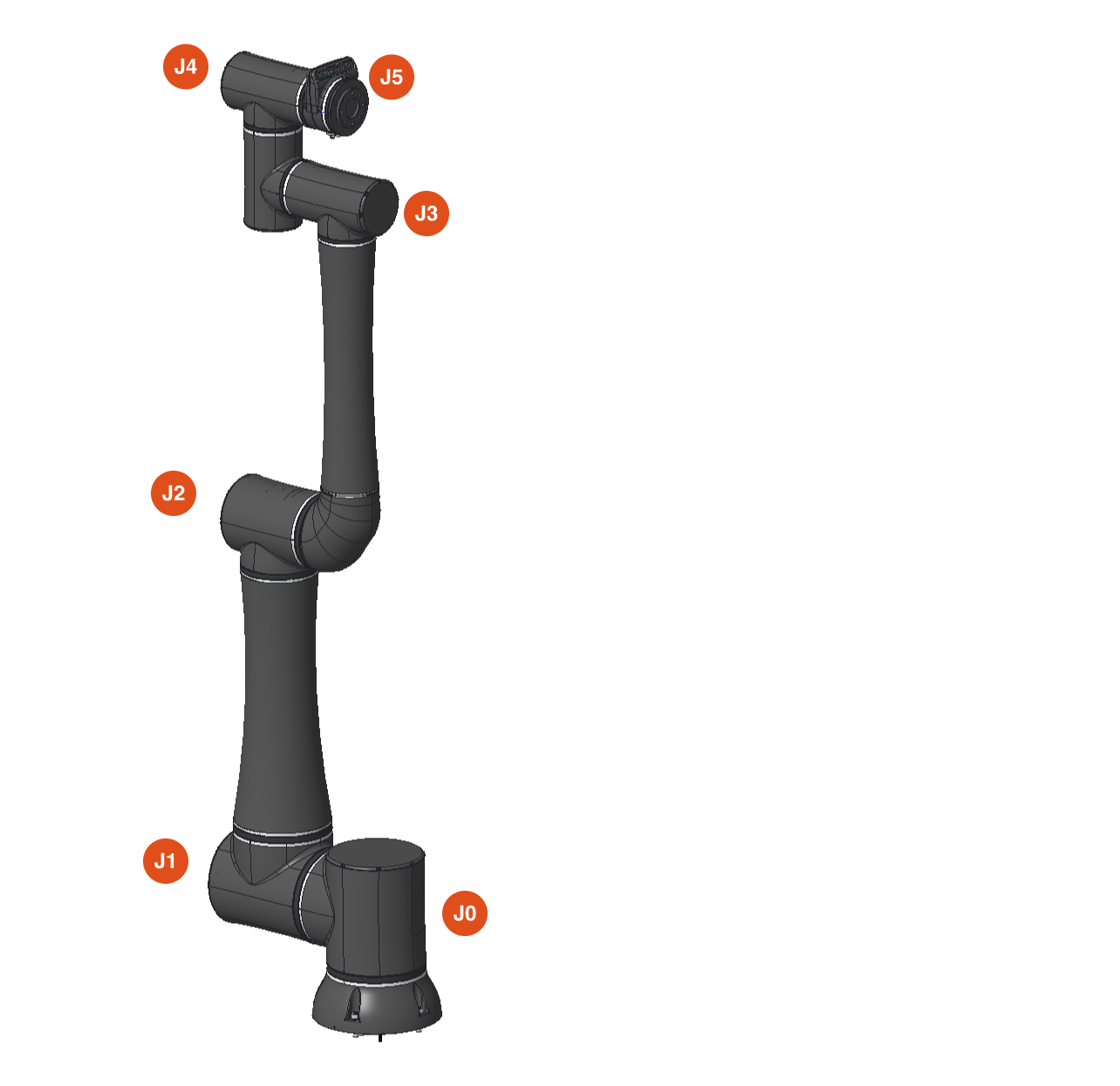
2.1.1 Overview
The Core arm contains 6 joints connected by a CAN bus. Each joint has two encoders, two different methods to sense torque, and fail-safe brakes that provide emergency braking torque when power is removed from the arm.
2.1.2 Reach
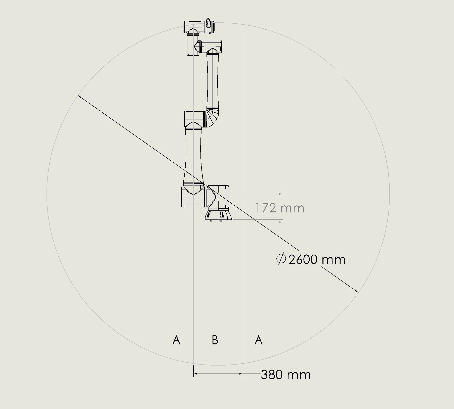
The Core robot can reach 1300 mm (51.2 in) in a radius from the center of the base (A). There is a radius from the center base of 190 mm (7.5 in) (B) where the robot cannot reach due to its structure. Tools added to the robot end of arm will impact the reach of the robot.
2.1.3 Payload Chart
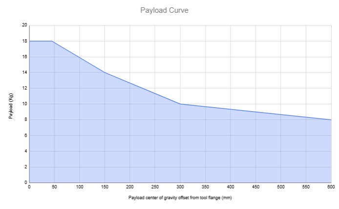
Footnotes:
At payloads above 16kg, the maximum speed of the robot will be reduced to 25% of the default speed settings. The default tooltip speed is 0.75 m/s.
At payloads above 16kg, the weight limit may be reduced if the routine includes stops with the arm near full extension.
The above chart assumes near ambient room temperature. Running the robots in warmer environments will reduce payload capacity.
2.1.4 Tool Flange Pinout
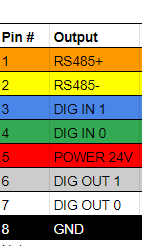
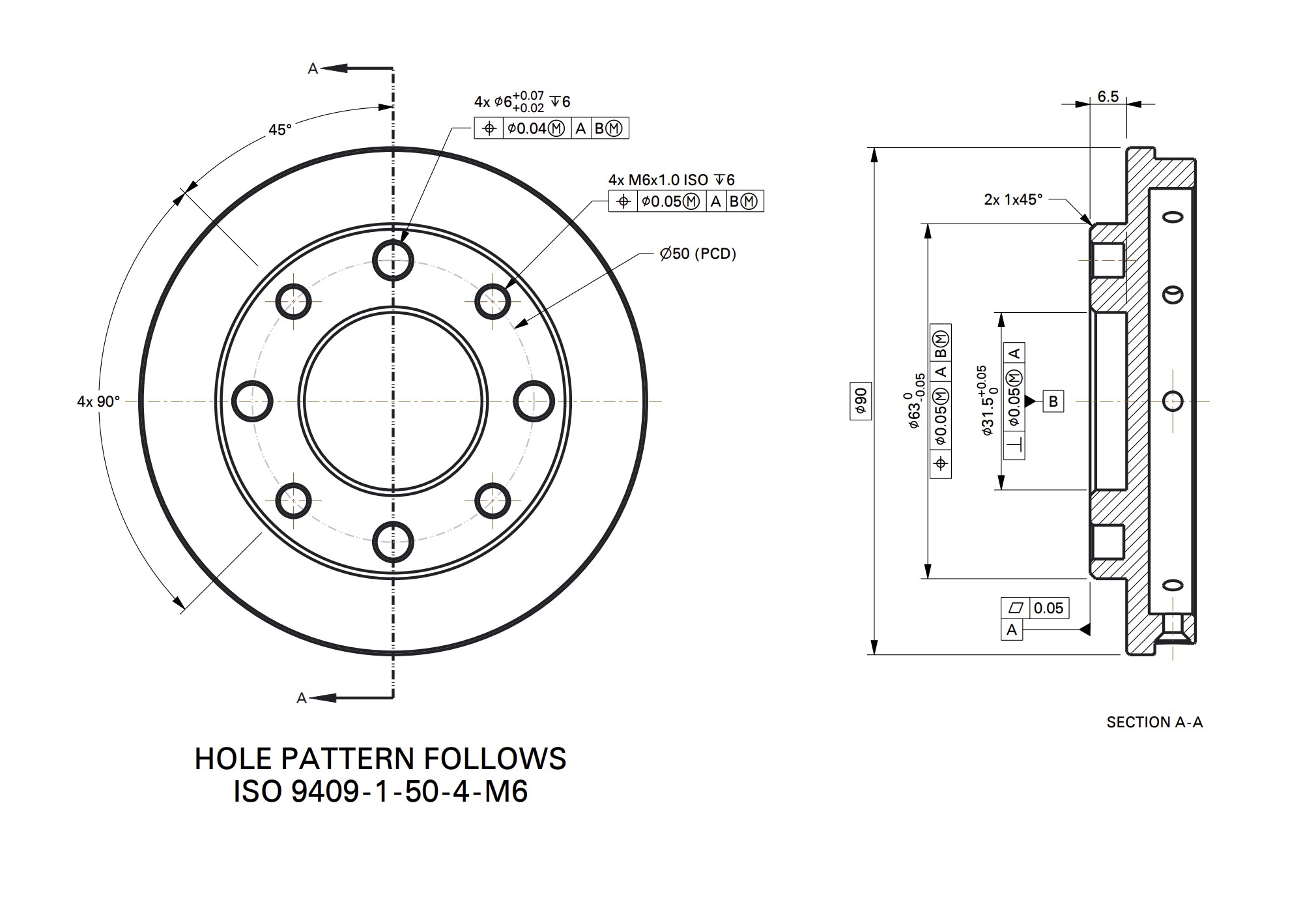
The current limit on the 24V DC line of the flange is 3 amps. The flange is capable of PNP or NPN operation and is auto switching. Please ensure the robot is powered off when connecting tooling to the m8 port to reduce risk of any shorting during the connection process. The pinout at the end of the Tool Flange is laid out as shown:
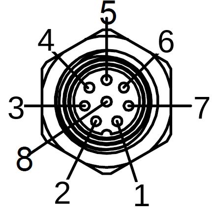
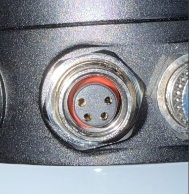
Also, please note that the 4-pin connector at the tool flange is not currently supported.
2.1.5 Supported End Effectors
Core supports a range of integrated end-of-arm tools (EOATs) including OnRobot 2FG7, 2FG14, 3FG15, and Dual Changer, plus Schunk EGU and EGK grippers. Any tool driven via discrete 24V I/O can also be actuated through the Standard Bots routine editor. See Connecting End Effectors in the Assembly & Setup chapter for the full integration list and connection instructions.
Payload note: When operating with an end effector and payload, the combined mass counts toward the robot’s payload limit. At payloads above 16 kg, maximum robot speed is automatically reduced to 25% of default settings. See the Payload Chart above for derating curves.
2.1.6 LED Colors
The robot end of arm has an LED status light for assisting in determining the robot status. The color codes are as follows:
| Robot State | Color |
|---|---|
| Idle or Paused | Solid Green |
| Bootup / Startup | Color Cycle |
| Full Speed (above collaborative threshold in Safety Settings) | Yellow Ring Pattern |
| Reduced Speed (below collaborative threshold in Safety Settings) | Solid Yellow |
| Antigravity Mode | Solid Blue |
| Firmware Update | White Ring Pattern |
| Recoverable Error | Red Pulsing |
| Fatal Error | Braked |
2.2 Control Box
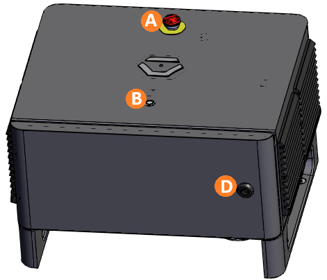
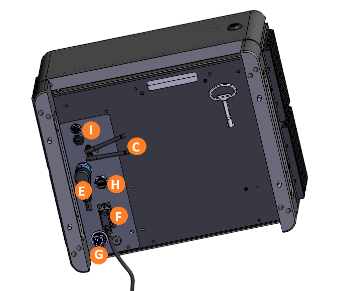
There are several features to note on the control box:
| Item | Name | Description |
|---|---|---|
| A | E-Stop | Pressing the E-stop button initiates an emergency (category 1) stop, cutting power to the arm. Twist the button to reset it. |
| B | Button Control | Turn on button |
| C | Bluetooth & Wi-Fi Antennae | Core ships with two antennas that can be screwed into the top to give the control box access to Bluetooth and Wi-Fi. Bluetooth is used to pair the tablet. |
| D | Lock & Key | Core includes a key that can be used to lock the control box door. |
| E | Arm data + power connection | This links the control box to the arm. |
| F | Power | The control box accepts 120V through a power supply module already certified to IEC 62368-1 and FCC EMI limits. |
| G | Ethernet (RJ45) | This can be used to communicate with other devices in the cell, or to the tablet for programming |
| H | USB-A port | |
| I | USB-C port | This links the control box to the camera on the robot arm |
2.2.1 Front Panel
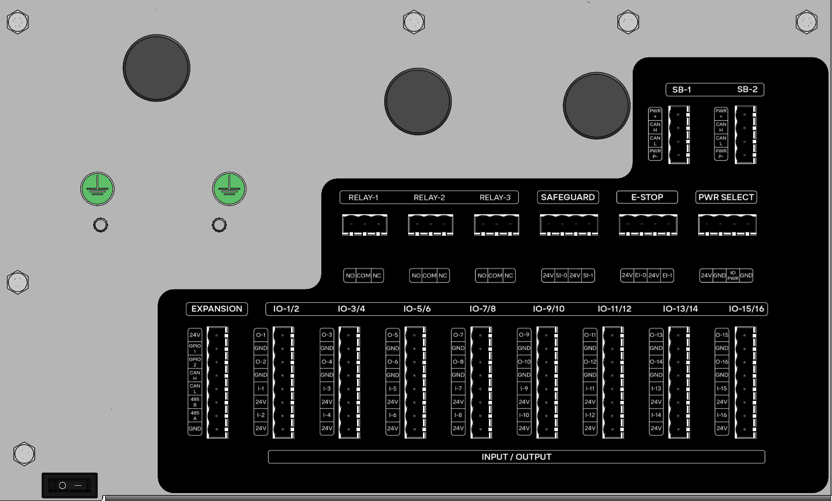
Inside the front panel are many ports that can be used to connect the robot to other equipment in the cell:
| Section | Port Labels | Description |
|---|---|---|
| I/O - 1 and 2 | DI, 24V, GND | This section includes 16 24V I/O ports which can be used to control other equipment in the cell. They are also safety-rated and can be used in pairs to activate safety functions of the robot via the Safety I/O feature. |
| Relay | RL-1, RL-2, RL3 | The relays can be closed to form a circuit and can be used to control equipment in the cell. |
| Safeguard | - | Unsupported. |
| E-Stop | - | This can be hooked up to an external E-stop button. When the input is low, it will force the robot to stop. If no external E-stop button is in use, these ports should have jumpers installed. |
| Motor: | M-1, M-2 | Unsupported. |
| Remote On/Off | ROFF, RON, GND, 24V | Unsupported. |
| Comms | PWR, GPIO 1+2, CAN H, CAN L, 485 A, 485B | Unsupported. Future software will enable communication with other equipment in cell over serial ports. |
2.3 Environmental & Operating Limits
The Core robot and control box are designed to operate safely within the following environmental constraints:
| Parameter | Specification |
|---|---|
| Ambient Temperature | 0–55°C (32–131°F) |
| Humidity (non-condensing) | 90% RH |
| Noise Level | <58 dB (typical, program-dependent) |
| IP Classification (Robot) | IP54 |
| IP Classification (Control Box) | IP54 |
| Mounting Orientation | Floor mount only |
Notes:
- IP54 means the robot and control box are protected against dust ingress and low-pressure water jets from any direction. They are not sealed for submersion or high-pressure washdown.
- Ambient temperature affects payload capacity; operation in warmer environments reduces maximum payload (see Payload Chart above).
- Humidity must remain non-condensing to prevent electrical shorts or corrosion inside the robot or control box.
- Noise levels vary with joint speeds, acceleration rates, and routine complexity. Maximum noise occurs during full-speed, high-acceleration movements.
2.4 Specs
| Performance | |
|---|---|
| Power consumption | Depends on program and payload; range from 25W to 1500W. Does not exceed 15 amps at 120V. |
| Collaboration operation | Speed & force limiting per ISO/TS 15066, collision detection, and other safety features |
| Ambient temperature range | 0-55°C |
| Humidity | 90%RH (non-condensing) |
| Specification | |
|---|---|
| Payload capacity | 18kg (39 lbs) maximum. See chart above. |
| Reach | 1.3m (51.2 in) |
| Max joint speed | 435° /s |
| Degrees of freedom | 6 degrees |
| Physical | |
|---|---|
| Footprint | Ø 200 mm |
| Materials | Aluminum, steel, plastic |
| Tool connector type | M8 8-pin & M8 4-pin |
| Cable length, robot arm | 2m (79 in) |
| Weight, including cable | 32.5 kg (71.6 lbs) |
| Robot Features | |
|---|---|
| IP classification | IP54 |
| Noise | Depends on program; typically less than 58dB |
| Robot mounting | Floor mount |
| Flange I/O ports | Digital In: 2 (24V tolerant, 1A max open-drain), Digital Out: 2 (Open-drain or push-pull, 1A), RS-485 / UART Max data rate: 10mbps |
| I/O power supply in tool | 12V/24V, 3A continuous max |
| Control Box | |
|---|---|
| IP classification | IP54 |
| Ambient temperature range | 0-55°C |
| I/O ports | Digital In: 16 (24V Tolerant), Digital Out: 16 (24V 0.7A Out continuous), |
| Internal I/O power supply | 24V, 3A max continuous. |
| External I/O power supply | 12A Maximum |
| Communication | 24V I/O, Modbus TCP, Ethernet IP, APIs over Ethernet |
| Power source | 90 ~ 264VAC, 47-63Hz |
| Humidity | 90%RH (non-condensing) |
| Control box size | 483mm x 385mm x 270mm (19.0in x 15.2in x 10.6in) |
| Weight | 18.5kg (41 lbs) |
| Materials | Powder-coated steel |
| Movement | |
|---|---|
| Repeatability | +/- 0.025 mm |
| Shoulder 1 & 2 | Working range: ±360°, Maximum speed: ±287°/sec |
| Elbow | Working range: ±360°, Maximum speed: ±335°/sec |
| Wrist 1, 2 & 3 | Working range: ±360°, Maximum speed: ±435°/sec |
| Typical TCP speed | 1 m/sec (39.4 in/sec) |
| Maximum TCP speed | 3 m/sec (No payload) |
2.5 Hazardous Energy
2.5.1 Overview
Stored energy is a potential source of danger in many industrial settings. When energy is stored in machines or equipment, it can cause serious injury or death if it is released unexpectedly. This type of hazard is commonly known as hazardous stored energy, and it can take many forms, including electrical, hydraulic, pneumatic, chemical, and mechanical energy.
Some common examples of hazardous stored energy include:
- A compressed air cylinder that has not been properly vented before maintenance or repair work is performed
- A hydraulic cylinder that has not been properly locked out before maintenance or repair work is performed
- A battery that is still connected to a piece of equipment, even though the equipment has been shut down
- A piece of machinery that is still moving, even though the power has been turned off
To protect workers from hazardous stored energy, it is important to follow proper lockout/tag-out procedures. Lockout/tag-out procedures involve shutting off the energy source, isolating the equipment, and securing it with a lock or tag to prevent accidental startup. Before any maintenance or repair work is performed on equipment, workers should always verify that the equipment is properly locked out/tagged out.
Additionally, workers should receive proper training on lockout/tag-out procedures and the potential hazards associated with hazardous stored energy. They should understand the importance of following these procedures to prevent injuries and fatalities. Employers should also regularly review and update their lockout/tag-out procedures to ensure that they are effective and up-to-date with the latest safety standards.
Remember, hazardous stored energy can be deadly if not properly controlled. By following proper lockout/tag-out procedures and receiving proper training, workers can stay safe on the job and prevent accidents from occurring.
2.5.2 Hazardous Energy in Standard Bots System
Several types of stored energy can exist in a system utilizing a Standard Bots robot:
Electrical: The Standard Bots control box utilizes 120 VAC power as a primary means of power. The control box utilizes electrical devices such as capacitors which store electrical energy even after the control box has been unplugged from the power source. There are no serviceable parts inside Standard Bots control box and it should not be opened except by trained Standard Bots Employees.
Additionally, the Standard Bots Core robot also contains capacitors to store electrical energy. The robot should not be opened except by Standard Bots personnel. In some cases it may be required to open the joint caps of the robot. This should only be done after the control box power source has been unplugged for at least 2 minutes, and should only be done by Standard Bots personnel.
Mechanical: The Standard Bots Core is capable of lifting 39 lbs (18kg). If the robot is stopped mid cycle and currently has a workpiece in the end of arm tool, a hazard will be present as the workpiece could unexpectedly fall if the source providing the clamping force is de-energized. Always exercise caution and remove the workpiece from the end of arm tool when approaching the robot.
Pneumatic: Core is compatible with a variety of pneumatic accessories. Stored energy exists in the form of compressed air in pneumatic systems. Bodily or hearing injury can occur from accidentally releasing compressed air from pneumatic systems while performing maintenance. Unexpected motion can occur from components when working on energized pneumatic systems. All compressed air should be removed from the system before performing maintenance on any pneumatic system.
2.5.3 Performing a Lockout
Should a lockout of the Standard Bots Core be required, unplug the AC input cord and use a plug lockout with appropriate lock. Follow all standard lockout tag-out procedures.
If applicable, also lock out any compressed air sources to devices integrated with Core using standard lockout tag-out procedures.
2.6 Anti-Gravity Mode
Anti-gravity mode allows you to physically move the robot by hand. This can be useful for teaching waypoints or positioning the robot. To enable anti-gravity mode, press the Raise button on the robot. The LED at the end of the arm will turn solid blue when anti-gravity mode is active.
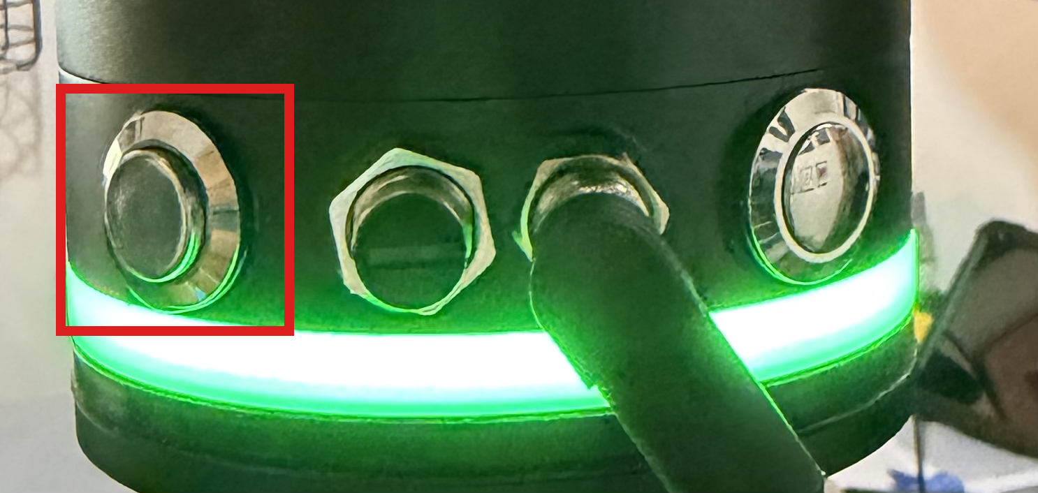
Warning: Anti-gravity mode should only be used if the risk assessment approves its use. Ensure the work area is clear before enabling this mode.
2.7 Movement Without Drive Power
Do not attempt to move Core without drive power unless instructed by Standard Bots personnel, otherwise damage could occur.
Core is a collaborative robot, and is designed to work in environments alongside humans. As such, under normal circumstances moving the robot without drive power is not required. Should the robot position need to be changed, simply use pendant to jog the robot into the required position.
Should you be instructed to move the robot without drive power by Standard Bots personnel, the below procedure can be used on each joint individually to adjust the robot position:
Unplug the robot.
Remove the cover on either Joint 0 or Joint 1 (bottom 2 joints, shown in attached image) by twisting it off.
Press the brake release button (shown in below image) and hold down while moving joint.
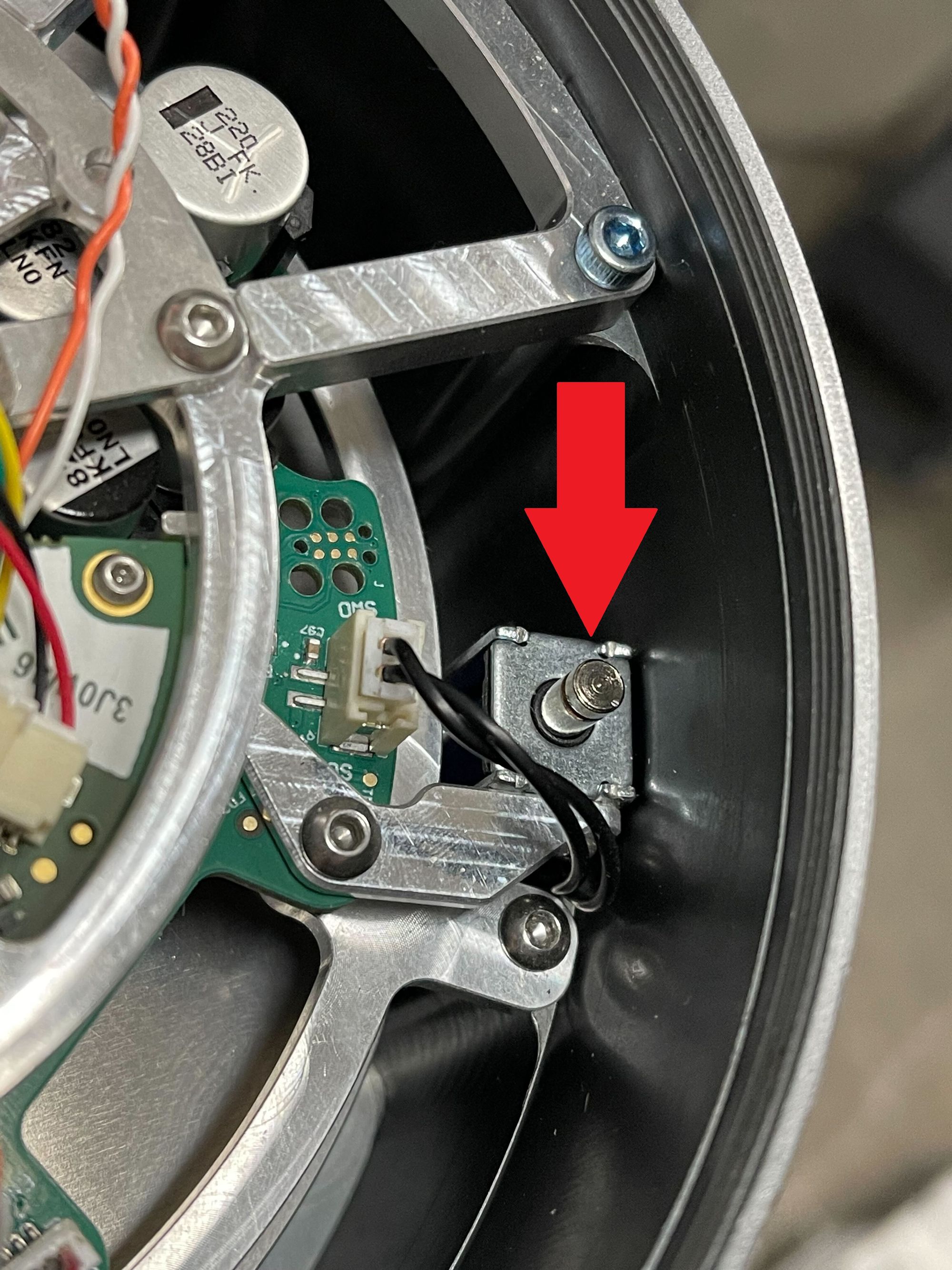
Move the robot away from the collision a short distance.
Release brake button.
Replace joint cap.
Plug the robot back in.
Confirm proper robot operation.