
3 Assembly & Setup
3.1 Requirements
The Core robot has the following utilities requirements:
| Utility | Requirement |
|---|---|
| Electrical | 90 ~ 264VAC, 47-63Hz, 15 A maximum at 120VAC. |
| Internet | Wi-Fi or RJ45 (Ethernet) wired connection for remote updates and support. |
| Floor | Mount to a structurally sound concrete floor or engineered base per local codes |
3.2 Lifting the Core
Core must be moved using proper lifting practices. The Core arm assembly weighs approximately 32.5 kg (71.6 lb) including cable. While Core can be lifted by two people, use proper lifting technique — lift with your legs, keep the load close to your body, and ensure the path is clear. Before lifting, ensure the arm is powered off, any end effector and payload are removed, and the work area is clear.
Lift slowly and smoothly to prevent swinging or rotation, and use a spotter as needed to guide the arm into position. If the lift or placement cannot be completed safely, stop and contact Standard Bots Support before proceeding.
Lifting and positioning must be performed by qualified personnel.
3.3 Assembly Procedure
3.3.1 Overview
This procedure describes how to mount and set up the Core robot arm. Core can be mounted to the Standard Bots portable base (included with most orders) or to a custom pedestal, table, or structure designed by the integrator. Regardless of mounting method, the mounting surface must be rigid enough to support the robot’s weight (32.5 kg) plus payload (up to 18 kg) without deflection during operation. A surface that flexes under load will degrade repeatability and may trigger false collision detections.
Do not power the robot until all mechanical fasteners are installed and torqued.
3.3.2 Mounting Requirements (All Installations)
- Rigidity: The mounting surface must be structurally sound and resist deflection under the robot’s full dynamic load. For custom mounts, steel or thick aluminum plate (minimum 12 mm / 0.5 in) bolted to a rigid structure is recommended.
- Level: The mounting surface must be level. The robot’s collision detection and gravity compensation assume a level mount.
- Bolt pattern: Core uses a twist-lock mechanism with 5× M8 × 30 mm screws to secure the arm to the arm mount plate. Your custom mount must accept the Core arm mount plate or replicate its bolt pattern.
- Cable routing: Ensure adequate clearance and strain relief for the power/data cable between the arm base and control box.
3.3.3 Option A: Standard Bots Portable Base
If you are using the Standard Bots portable base, follow the steps below.
3.3.3.1 Required Tools and Equipment
- Standard metric socket set
- Torque wrench (capable of 55 N·m)
- Level
- PPE (eye protection, gloves)
3.3.3.2 Step 1: Set Up the Base
- Place the Core base in its final intended location.
- Lock the casters by stepping on lock levers on each wheel.
- Adjust the 4 leveling feet until the base is level on the floor.
- Orient the base so the robot working envelope, cable exit, and service access are correct.
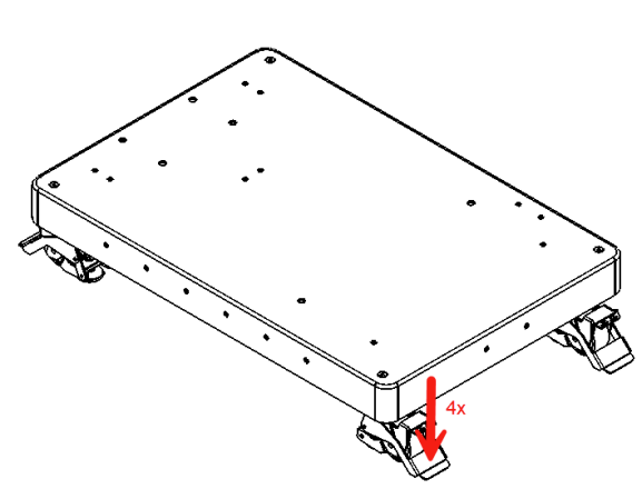
Note: For large payloads or extended work envelopes, optional floor brackets are recommended. Consult Standard Bots Applications Engineering for guidance. Four brackets can be anchored to the floor for added stability.
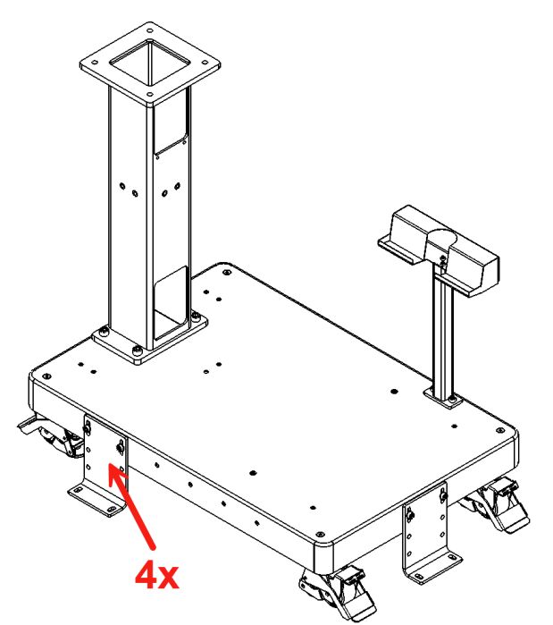
3.3.3.3 Step 2: Mount the Pedestal to the Base
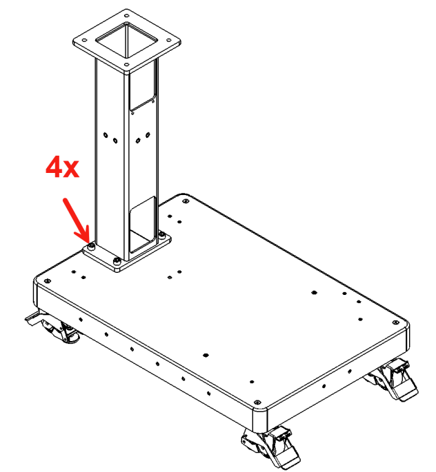
- Mount the pedestal to the base using 4× M12 × 1.75 mm, 25 mm hex socket screws.
- Torque to 55 N·m.
3.3.3.4 Step 3: Mount the Arm Mount Plate
The Standard Bots arm mount plate (drawing SB-192-F) provides the mounting interface between the pedestal and the Core arm. The plate is a 215 mm x 215 mm hard-anodized 6061-T6 aluminum plate with four M14 clearance holes (for mounting to the pedestal) and five M8x1.25 threaded holes on a 170 mm pitch circle (for the arm twist-lock).
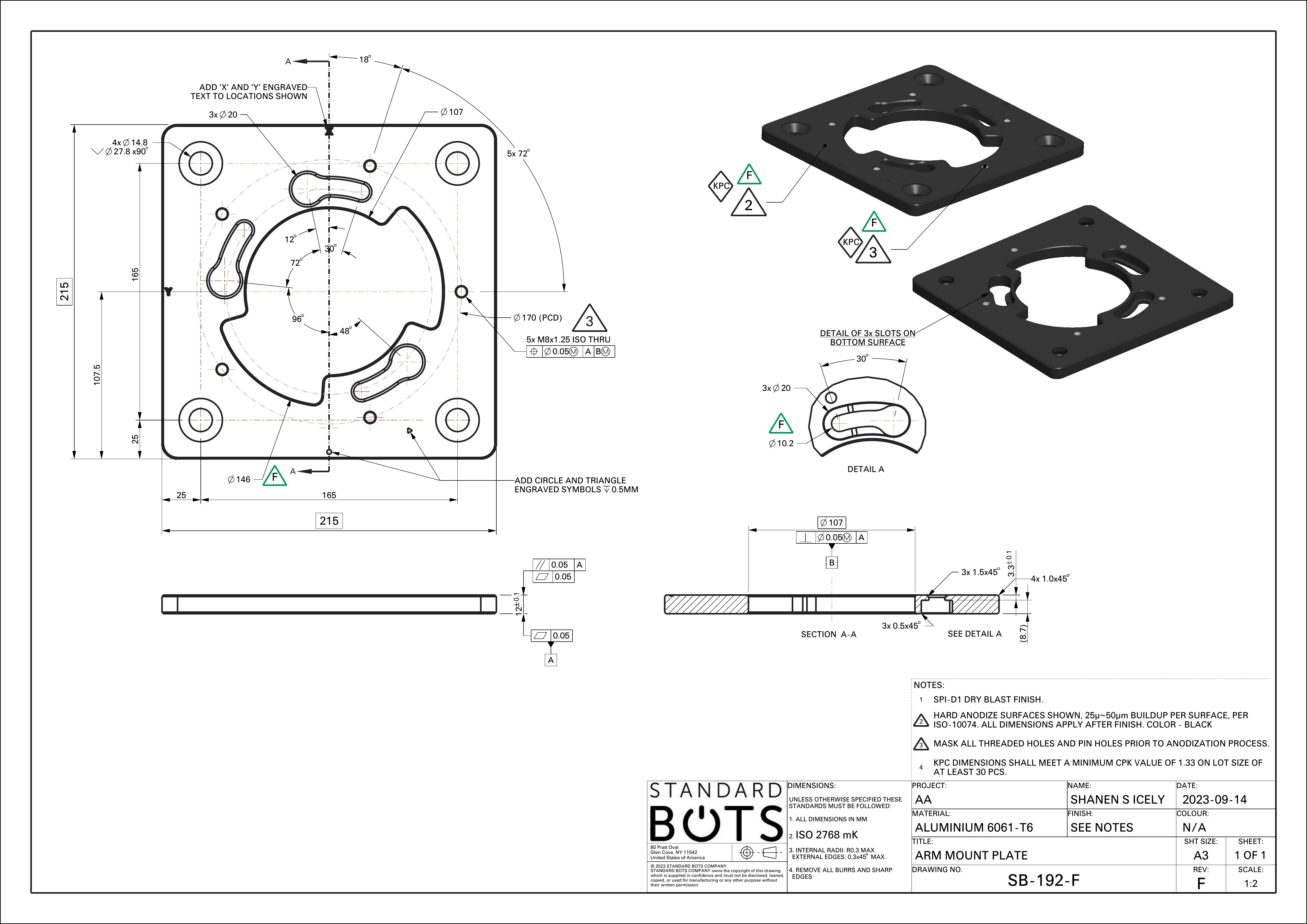
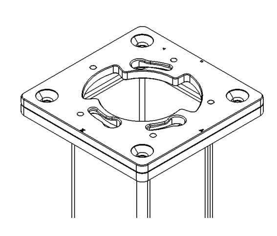
- Mount the arm mount plate to the pedestal using 4× M14 × 2.0 × 30 mm hex flat head screws.
- Torque to 55 N·m.
- The arm mount plate can be oriented in 4 directions (90° increments). Choose the orientation that positions the robot working envelope correctly for your application.
3.3.3.5 Step 4: Mount the Core Robot Arm
- Align the “O” marking on the robot base with the triangle indicator on the arm mount plate.
- Lower the robot onto the mount plate.
- Rotate the robot clockwise until the “O” on the robot base aligns with the matching “O” on the plate.
- Secure with 5× M8 × 30 mm screws.
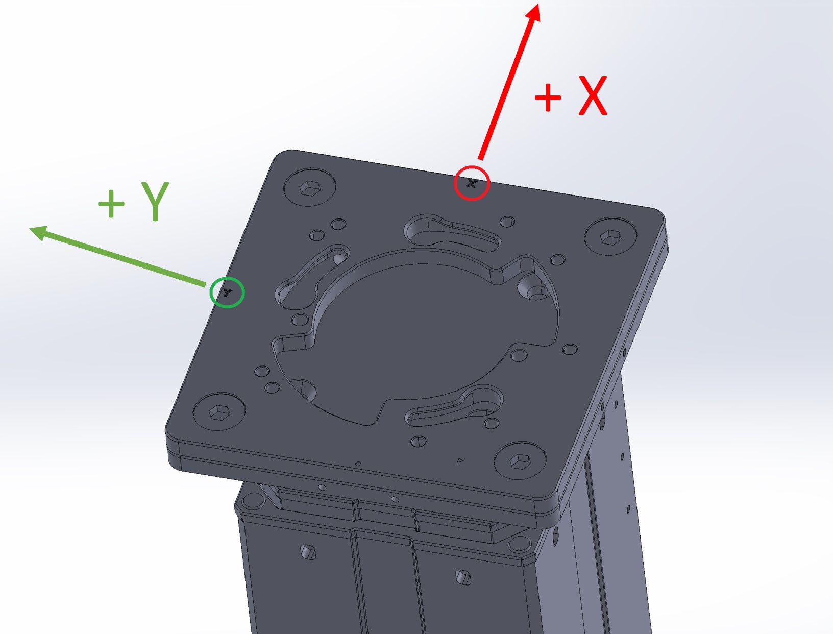
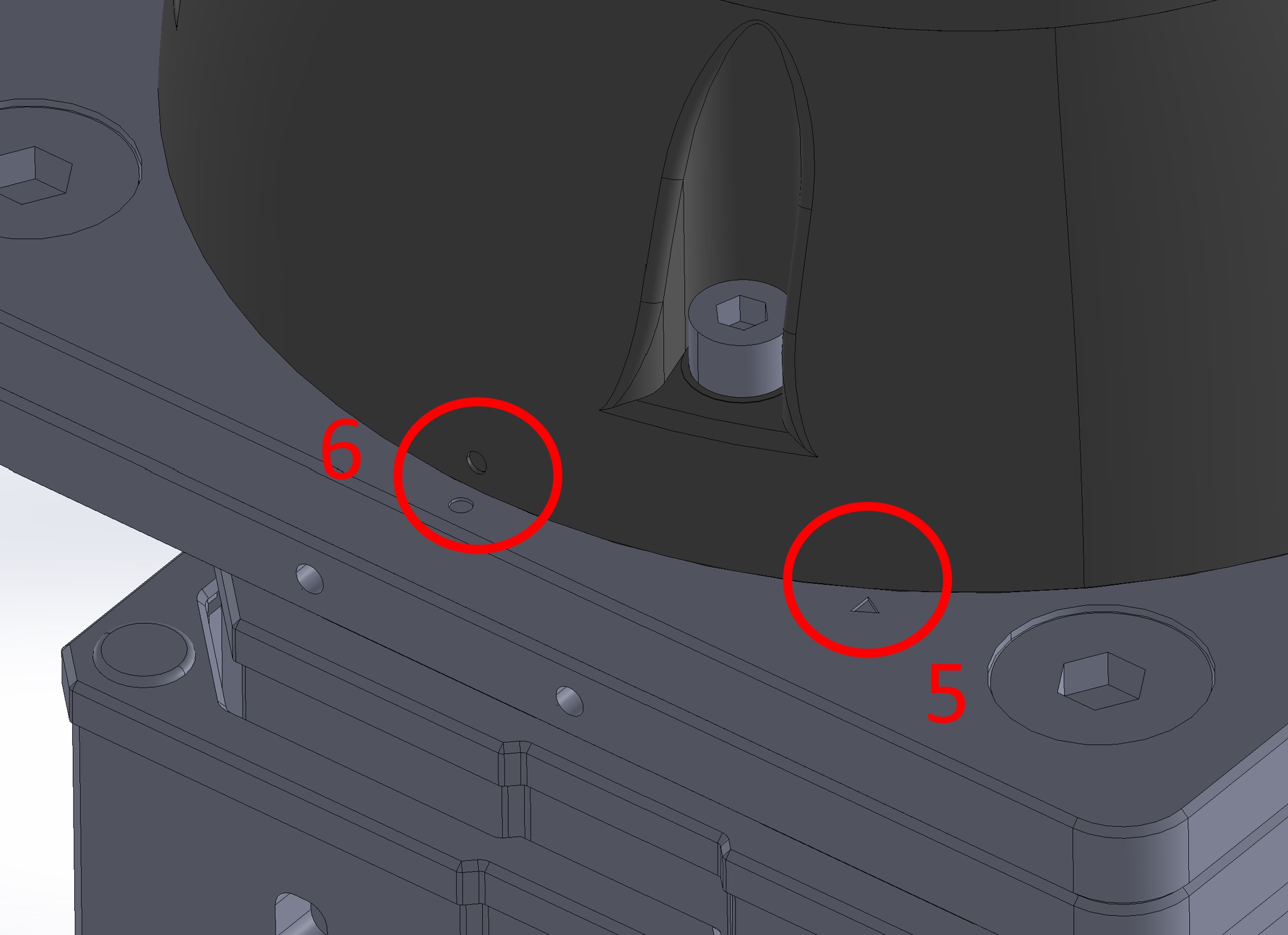
Note: The robot only attaches to the base in one orientation. X/Y markings on the base correspond to the tooltip orientation shown in the Move Robot view.
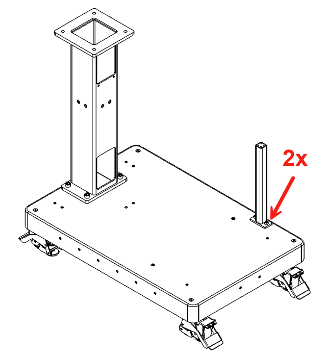
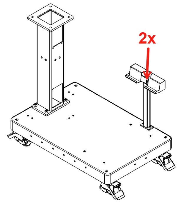
3.3.3.6 Step 5: Mount the Tablet Pedestal
- Mount the tablet pedestal to the base using 2× M8 screws.
- Torque to 6 N·m.
3.3.4 Option B: Custom Pedestal or Mounting Surface
If you are mounting Core to your own pedestal, table, or structure:
- Ensure your mounting surface meets the rigidity and leveling requirements described above.
- Secure the Standard Bots arm mount plate to your structure using appropriate fasteners for your material. The arm mount plate is the interface between the robot and any mounting surface.
- Mount the Core robot arm to the arm mount plate using the twist-lock mechanism and 5× M8 × 30 mm screws as described in Option A, Step 4.
- Position the control box in an accessible location near the robot, ensuring cable reach and strain relief.
For assistance with custom mounting configurations, contact Standard Bots Applications Engineering.
3.3.5 Prepare Cable Routing
Before powering on:
- Verify the robot cable path is clear through or alongside the base/structure.
- Ensure cables will not be pinched between the robot base and mounting surface.
- Confirm sufficient slack for full joint motion.
3.3.6 Secure Cables and Strain Relief
- Connect the USB-C, power, and data cables to the base joint.
- Install strain relief so connectors are not load-bearing.
- Verify cables have adequate slack and clearance.
3.4 Final Mechanical Checklist
Before power-on, verify:
- Mounting surface is rigid and level
- All structural fasteners torqued to specification
- Robot arm twist-locked and secured with 5× M8 screws
- Cables routed and strain-relieved
- No tools or debris remain on base or work area
3.5 Connecting Control Box
- If using the Standard Bots portable base, hook the control box onto the base bracket. For custom installations, place the control box in an accessible location near the robot.
- Connect the arm power/data cable to the port labeled Arm Data + Power.
- Connect Ethernet if required.
- Connect AC mains.
- Plug in the service USB-C and any maintenance leads into the control box; secure and tuck the cables.
- Verify E-Stop is released; power on; Confirm the control box indicates normal operation with no active faults.
3.5.1 Quick checks
- Cables are strain-relieved and not pinched.
- Verify the control box indicates normal operation before enabling motion.
3.6 Getting Connected
3.6.1 Setting up the Tablet
The included iPad is used to configure, control, and program Core. To set it up:
Take the iPad out of the box and turn it on.
If prompted at any point, enter the iPad’s default passcode: “000000” (on older shipments, try “0000”).
Connect the iPad to the Tablet USB-C port on the bottom of the Control Box and make sure the iPad is charging — if it is not, flip the USB-C cable 180 degrees on the Control Box side. Open the Settings app and confirm Ethernet appears in the sidebar below Wi-Fi.
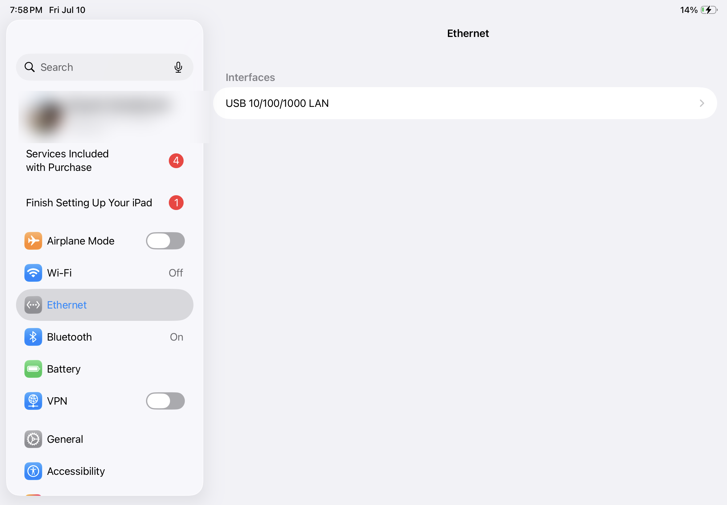
Note: If Ethernet does not appear, try a different USB-C cable or see Troubleshooting Connection Issues below.
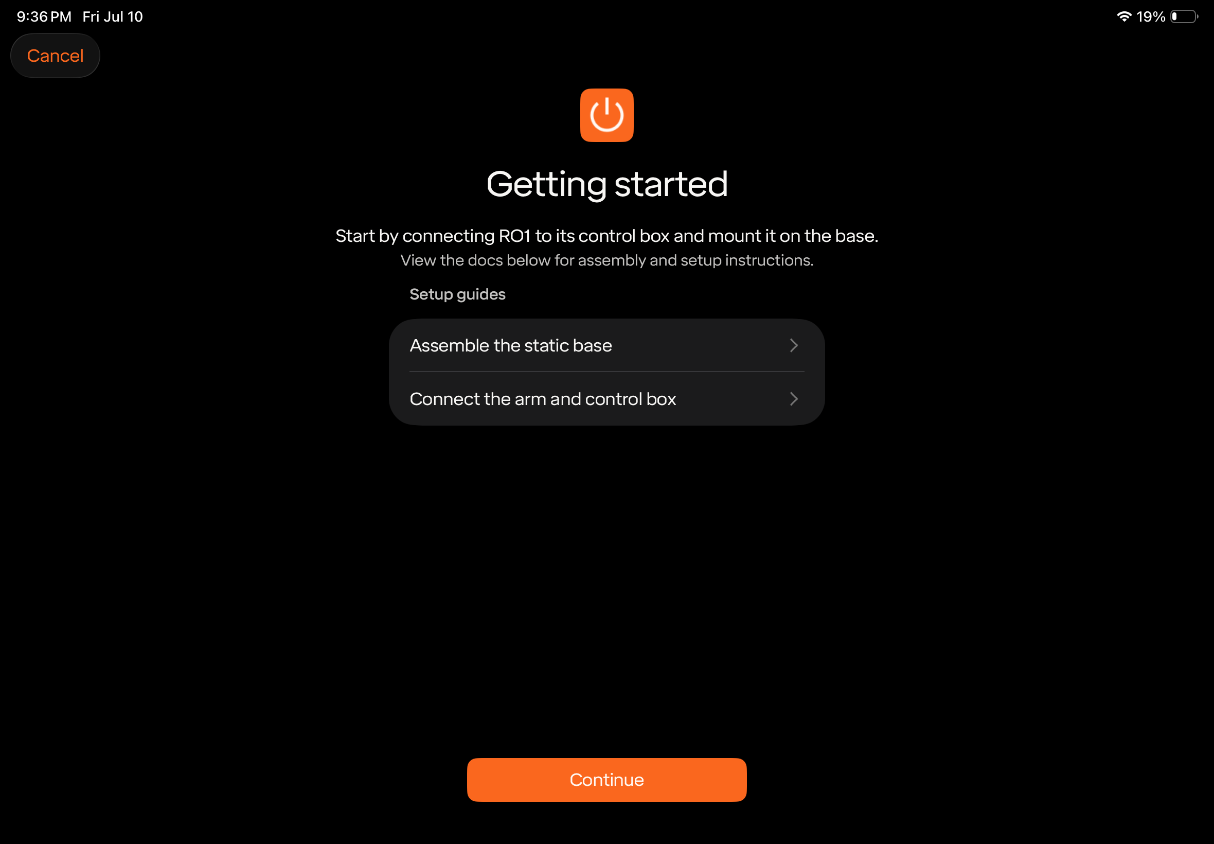
- Navigate to the home screen, open the Standard Bots app, and tap +Setup.
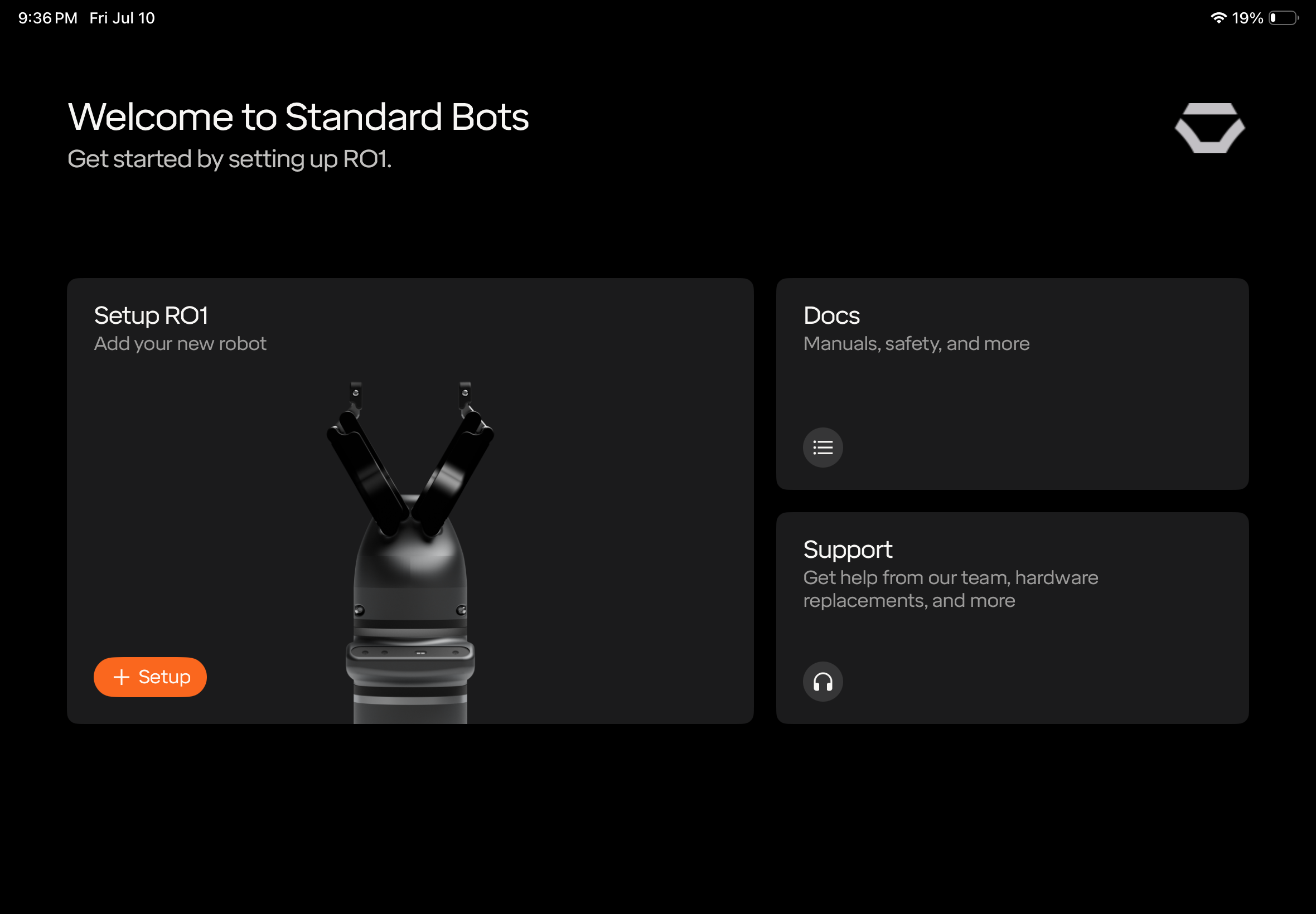
- On the Getting started page you will also find guides for assembling the robot base and connecting the robot arm to the control box. Once ready, press Continue.
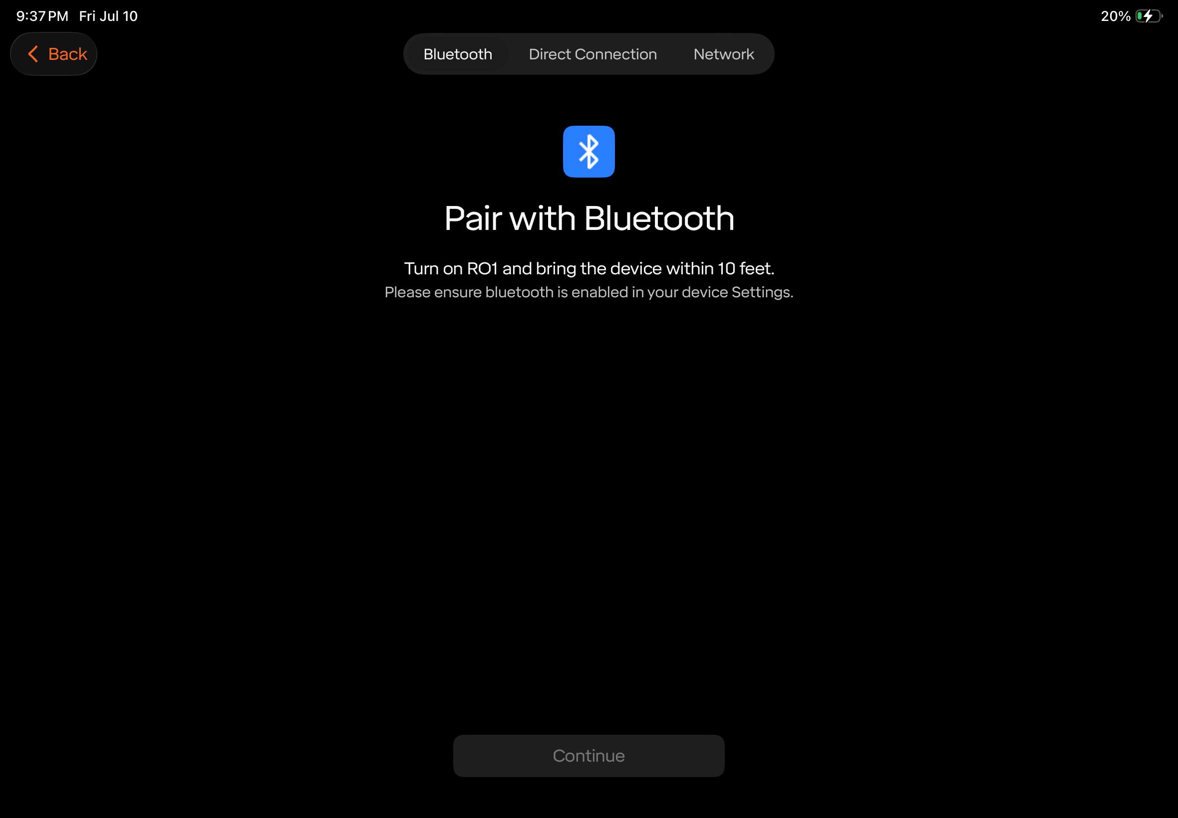
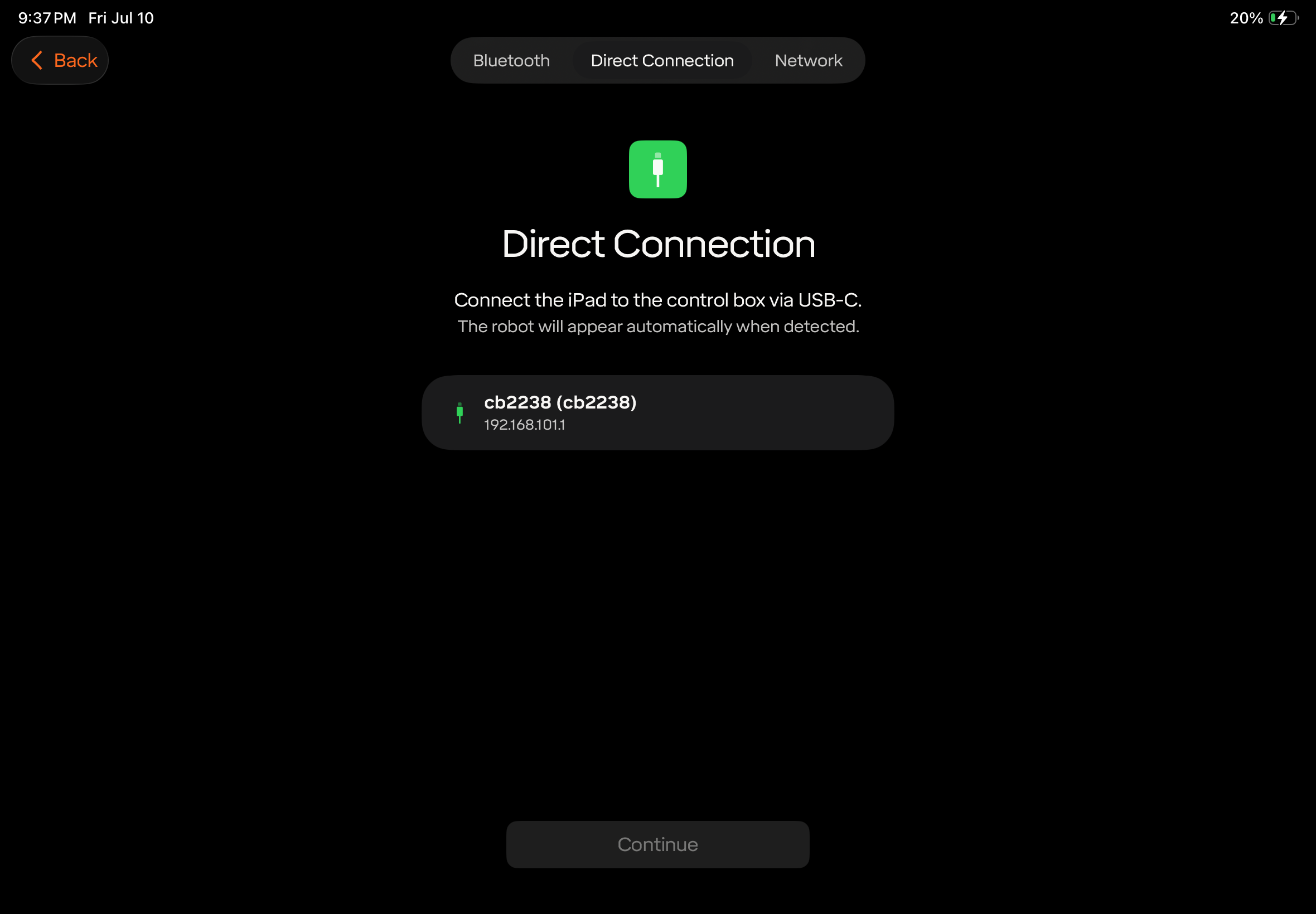
Choose how to find the robot, then select it and press Continue:
- Pair with Bluetooth — make sure Core is turned on and Bluetooth is turned on in the iPad settings.
- Direct Connection — with the USB-C cable connected, the robot appears automatically with its address (192.168.101.1).
Note: If the robot was previously set up, you may be prompted for its passcode. The default passcode is 000000 (or 0000 on software prior to 1.23).
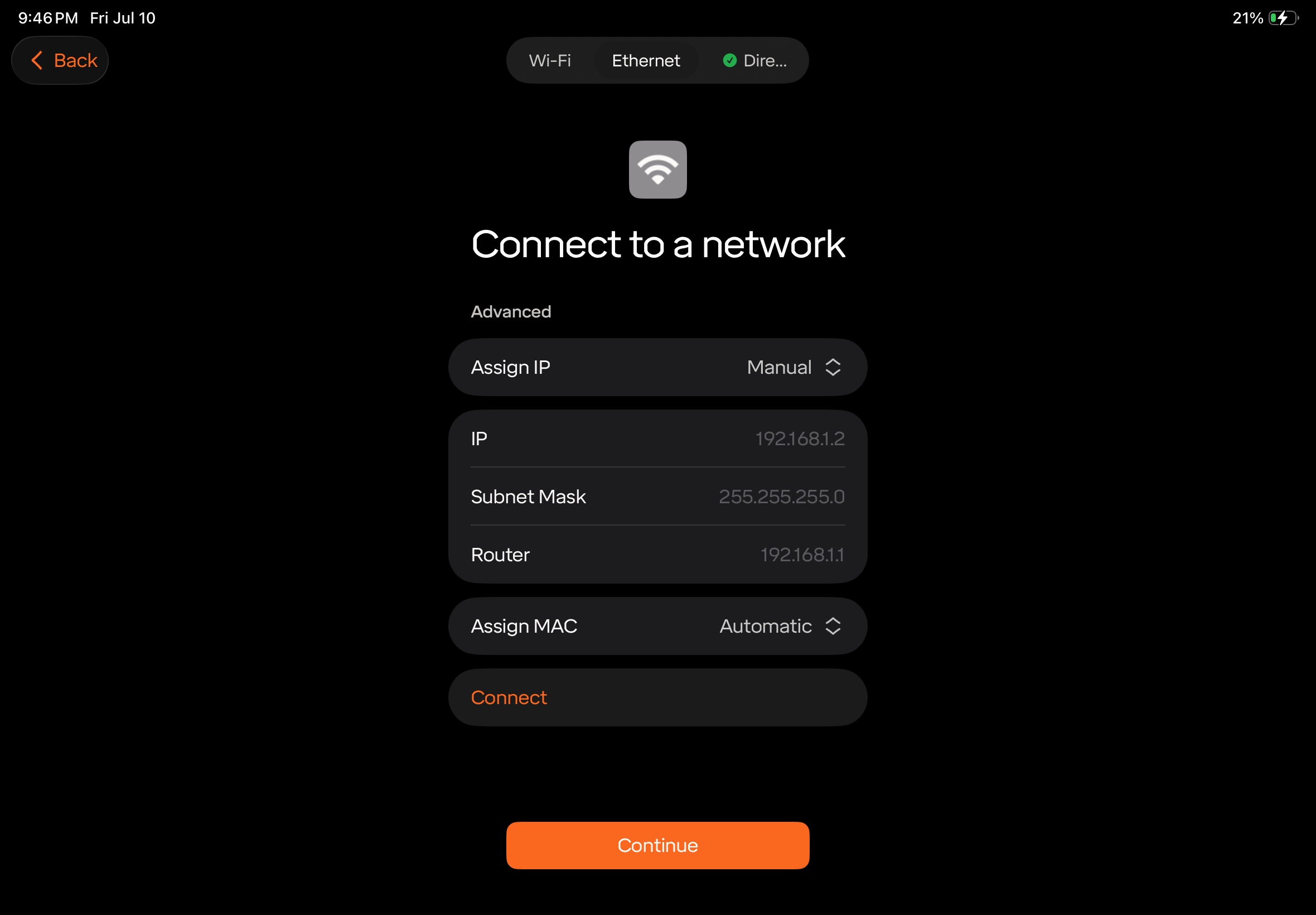
On the Connect to a network page, choose how the robot itself connects. This is independent of how the tablet is connected:
- Wi-Fi — the robot’s internal Wi-Fi card, powered through the antennas on the Control Box. Make sure the network does not require a splash page to access.
- Ethernet — the RJ45 Ethernet port on the bottom of the Control Box.
- Direct — the USB-C connection on the bottom of the Control Box.
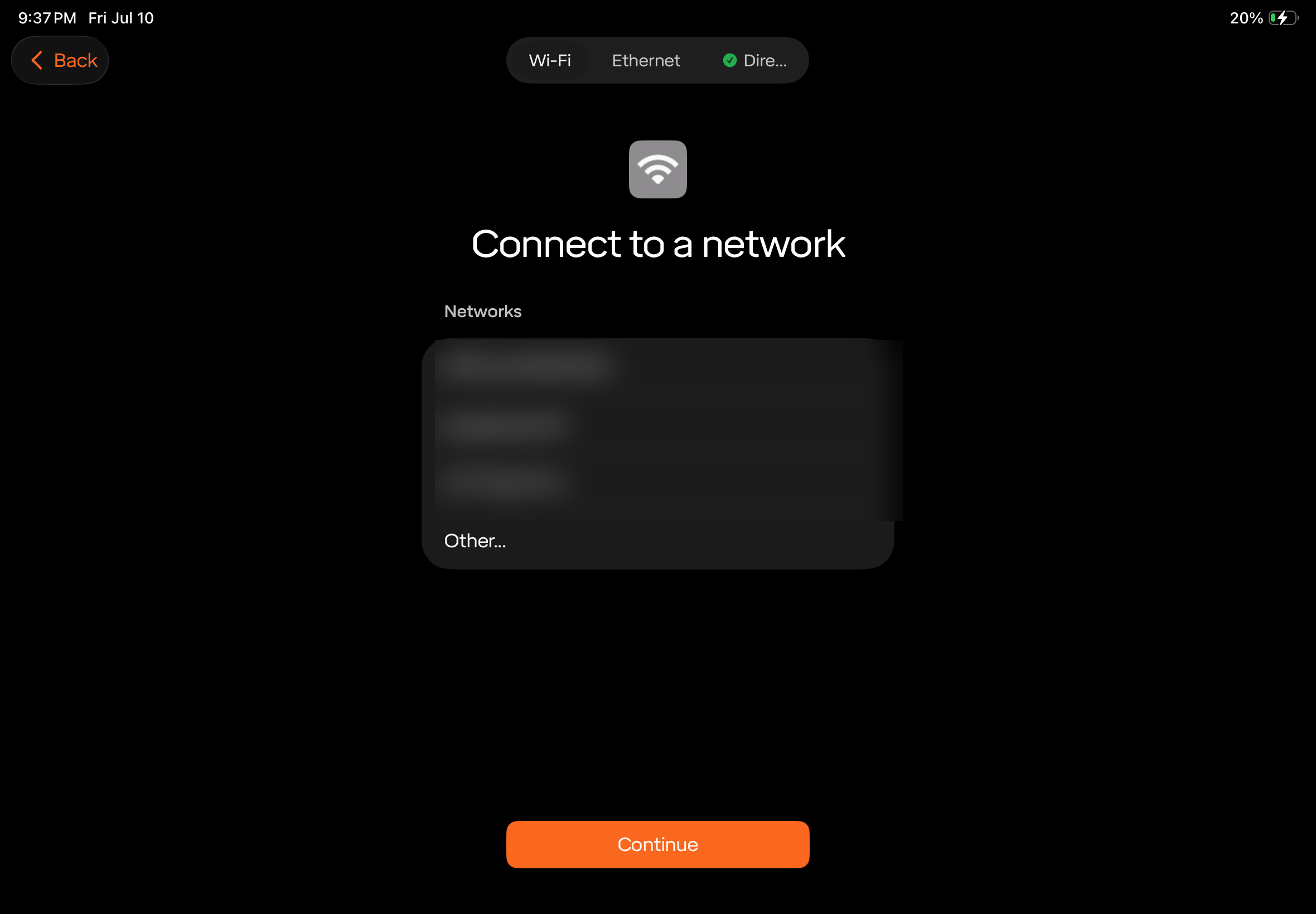
To give the robot a static address on your Ethernet network, select Ethernet, set Assign IP to Manual, and enter the IP, Subnet Mask, and Router for your network, then tap Connect.
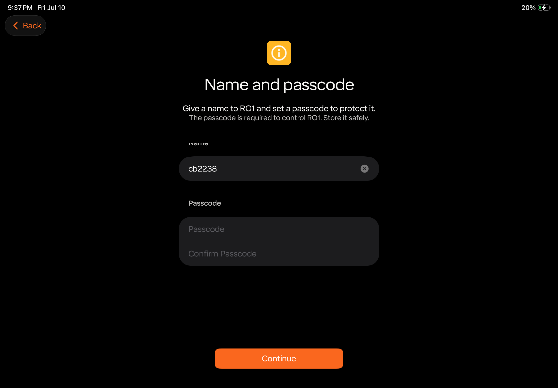
- Give the robot a name and set a passcode. The passcode is required to control the robot — store it safely.
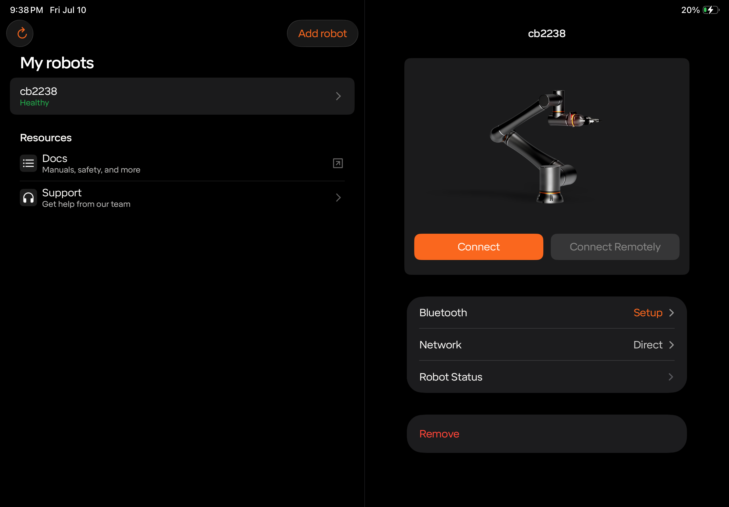
- When setup completes, the robot appears under My robots showing Healthy. Tap it and press Connect.
- Once connected, you can reset the E-Stop (if required), unbrake, and begin jogging the robot. For details on operating the robot, constructing routines, and programming, see the Standard Bots Programming Manual at programminghelp.standardbots.com.
3.6.2 Troubleshooting Connection Issues
If the iPad can’t find a new robot during initial setup, work through these steps in order and try connecting again after each one.
3.6.2.1 Basic Checks
- Confirm the Control Box is powered on. The LED on top of the box should be green. If it stays red, press and hold the button for at least 5 seconds — some Control Boxes do not start automatically when power is applied. If the LED and fans repeatedly start up and shut off in a cycle, the controller is failing to start — continue with the steps below, and contact support if it persists.
- Confirm the iPad charges from the Control Box. Plug the iPad into the Tablet USB-C port on the bottom of the Control Box. If the iPad does not begin charging, flip the USB-C cable 180 degrees on the Control Box side (the port is one-directional), or try a different USB-C data cable — charge-only cables will not work.
- Power-cycle the iPad.
- Power-cycle the Control Box. Disconnect anything wired to the Control Box IO ports and any end-of-arm tooling first — a miswired or shorted accessory can prevent the controller from starting. Power it off and wait for the fans to stop, give it ten or so seconds, then power it back on. Wait for the LED to turn green — if it stays red, press and hold it until it turns green. Try this both with the USB-C cable connected and with it disconnected.
- Update the iPad. Confirm iPadOS and the Standard Bots app are both on the most current versions.
- Check Bluetooth. Make sure Bluetooth is turned on in the iPad settings and the included antennas are screwed onto the Control Box, then confirm the robot appears when the app searches over Bluetooth. If another iPad is available, try it as well.
3.6.2.2 Check IP Settings
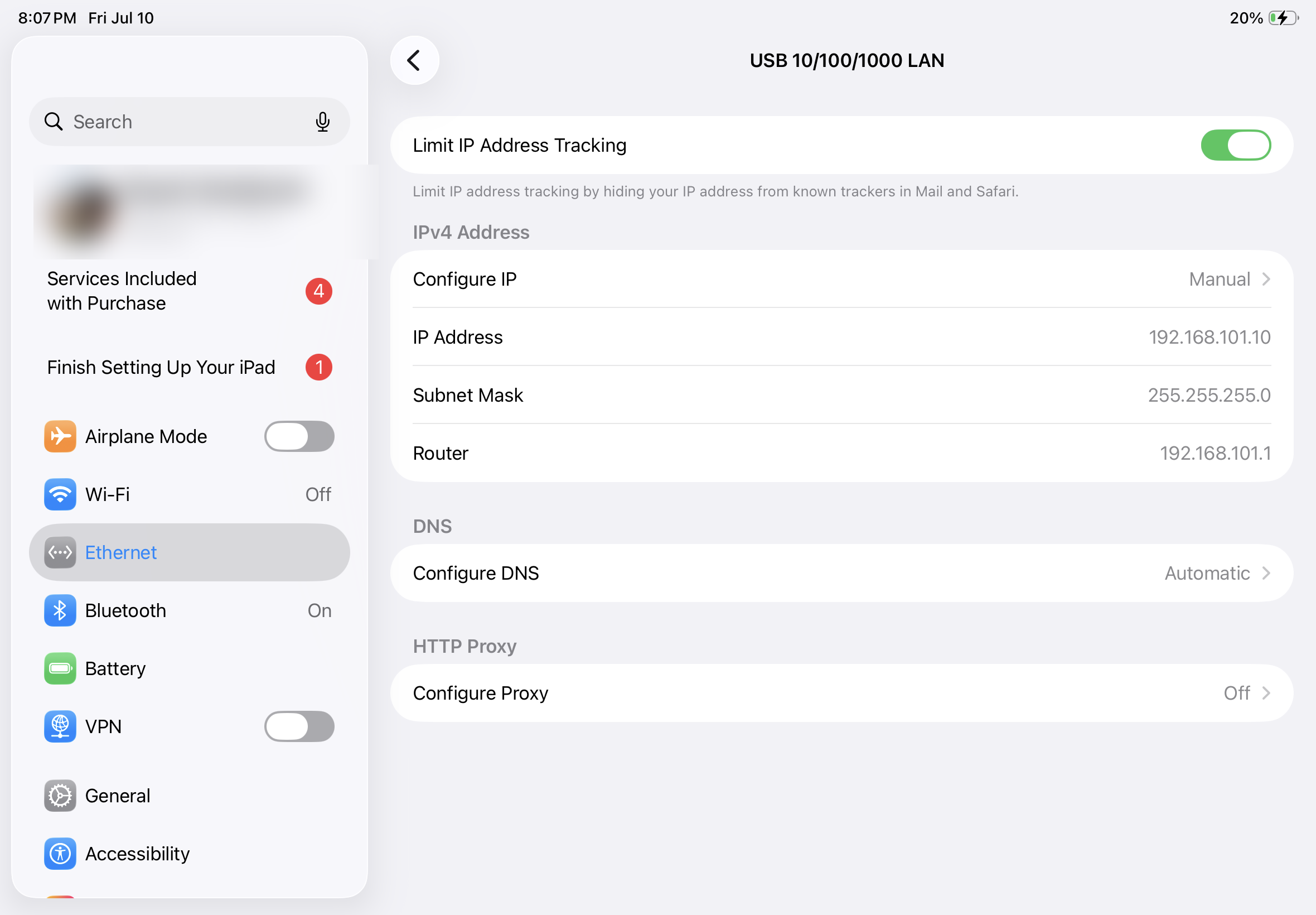
- Set the iPad’s IP address manually. With the USB-C cable connected, open Settings, tap Ethernet, then tap the USB 10/100/1000 LAN interface. Tap Configure IP, select Manual, and enter IP Address 192.168.101.10, Subnet Mask 255.255.255.0, and Router 192.168.101.1, then tap Save.
3.6.2.3 Connect Through a Web Browser
- Try the robot’s direct address. The Control Box’s direct (USB-C) connection always uses the address 192.168.101.1. On the iPad, open Safari and go to 192.168.101.1:3000 — the robot login page should appear.
- Try a PC. Connect a Windows PC to the Tablet USB-C
port with a USB-C data cable and turn off the PC’s Wi-Fi. You will need
to change the PC’s IP address to match the robot’s direct network. Press
Win + R, type
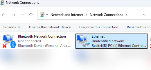
ncpa.cpl, and press Enter, then right-click the Ethernet adapter that appears for the USB-C connection and select Properties.
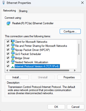
Double-click Internet Protocol Version 4 (TCP/IPv4), select “Use the following IP address,” and enter IP Address 192.168.101.10 with Subnet Mask 255.255.255.0, then click OK.
Then go to 192.168.101.1:3000 in a web browser. If that still doesn’t work, there are two more options:
- Internet Connection Sharing — share your PC’s
internet connection with the robot (Windows ICS) so the robot is
assigned an address automatically. The robot will receive an address in
the 192.168.137.x range — run
arp -ain Command Prompt to find it, then go to that address followed by :3000. If no address appears, check that Windows Firewall is not blocking UDP ports 67 and 68. - USB-C-to-Ethernet adapter — on the PC or on the iPad, with an Ethernet cable run from the adapter to the Ethernet port on the Control Box (see Appendix B: How to Direct Wire Core for the full iPad adapter procedure).
Once the login page loads, you can configure the robot’s network from the browser — see Changing the Robot’s Network Settings from the Browser below.
3.6.2.4 If Nothing Else Works
- Try the robot’s web address. If the robot was previously connected to the internet, go to cbXXXX.sb.app in a browser, where cbXXXX is the robot’s serial number found on the Control Box label. You can also plug the Control Box’s Ethernet port into an internet-connected network to give the robot outside access, then use this address (see Changing the Robot’s Network Settings from the Browser below).
- Scan the network. If the Control Box’s Ethernet port is plugged into your network, the robot should receive an address automatically — out of the box, the Control Box Ethernet is set to DHCP. Check that the link lights on the Ethernet port come on, then from a PC on the same network, network-scanning software (or your router’s client list) can detect the robot’s IP address.
- Connect a monitor. Plug a monitor into the HDMI port on the Control Box before powering on. If boot text appears on screen — even briefly — the controller is starting; if the screen stays blank through a full power cycle, the controller is not starting. Contact support with what you observed.
If none of these steps work, contact Standard Bots support with the robot’s serial number (cbXXXX, found on the Control Box label) and the list of steps you have tried.
3.6.3 Changing the Robot’s Network Settings from the Browser
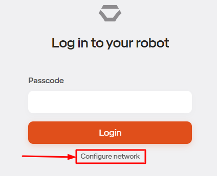
Once the login page loads, you can point the robot at your network without using the iPad app. Click Log Out at the top, then click Configure Network below the Login button. You will be asked for your passcode — on a robot that has never completed setup, this is the default passcode (000000, or 0000 on older software).
On the Network Setup page, check the box beside a network type to enable it:
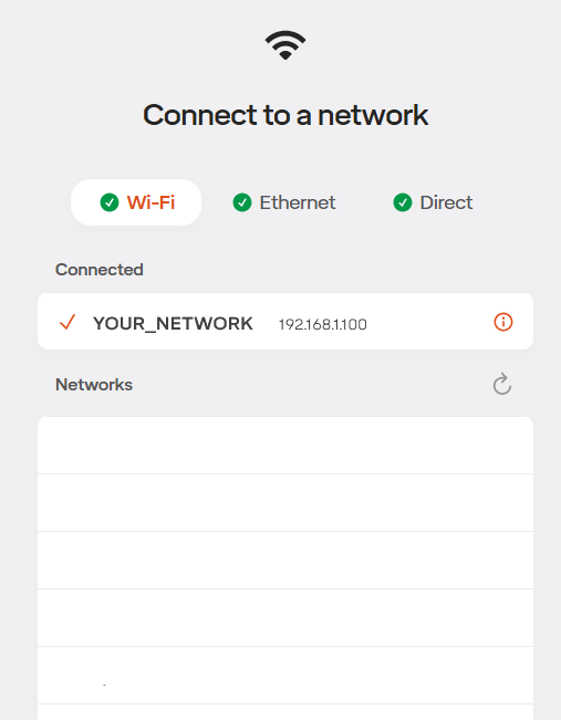
- Wi-Fi — recommended to be your company’s Wi-Fi network so the robot can be reached from programming PCs and tablets.
- Ethernet — the RJ45 port on the bottom of the Control Box, usually the machine network.
- Direct — the USB-C connection on the bottom of the Control Box.
After initial setup: once the robot’s Ethernet port is configured, you can confirm the robot is reachable on your network by pinging the IP address you assigned it from a PC on the same network.
Note: Robots running older software (12.08 and earlier) do not include this network settings page. If the login page loads but there is no Configure Network link, contact Standard Bots support to update the robot’s software.
3.7 Unmounting & Transporting
3.7.1 Warnings
- Do not attempt to move the arm while it has power.
- Do not force the robot into a position while power is off; doing so may damage the robot.
- Use proper lifting technique when handling the Core arm.
3.7.2 Before transportation:
- Ensure the robot is in the desired position for
transportation.
- If needed, the robot can be put into the position required for the
original box by:
- Navigating to the Move Robot view
- Go to the Robot menu in the upper right
- Select “Settings”
- Select “Box Robot”
- Save and confirm the Payload
- Click and hold down the “Move Live Arm To Visualizer Position” button. The robot will move into the packing pose.
- Click the hexagon button in the bottom right of the Move Robot view
- Select “Brake Robot”
- Unplug the control box from the AC power source
- Wait 30 seconds for stored power to dissipate
- Unplug the connector between the arm and control box by twisting the locking mechanism and pulling down on each end
- Disconnect any inputs and outputs from the control box
The Core control box has an integrated handle for ease of transportation. Ensure all cables are disconnected from the Core control box before moving or shipping the control box. Ensure Core control box is well packaged, preferably in the original packaging, before shipping the control box.
3.8 Connecting End Effectors
3.8.1 Mechanical Connection
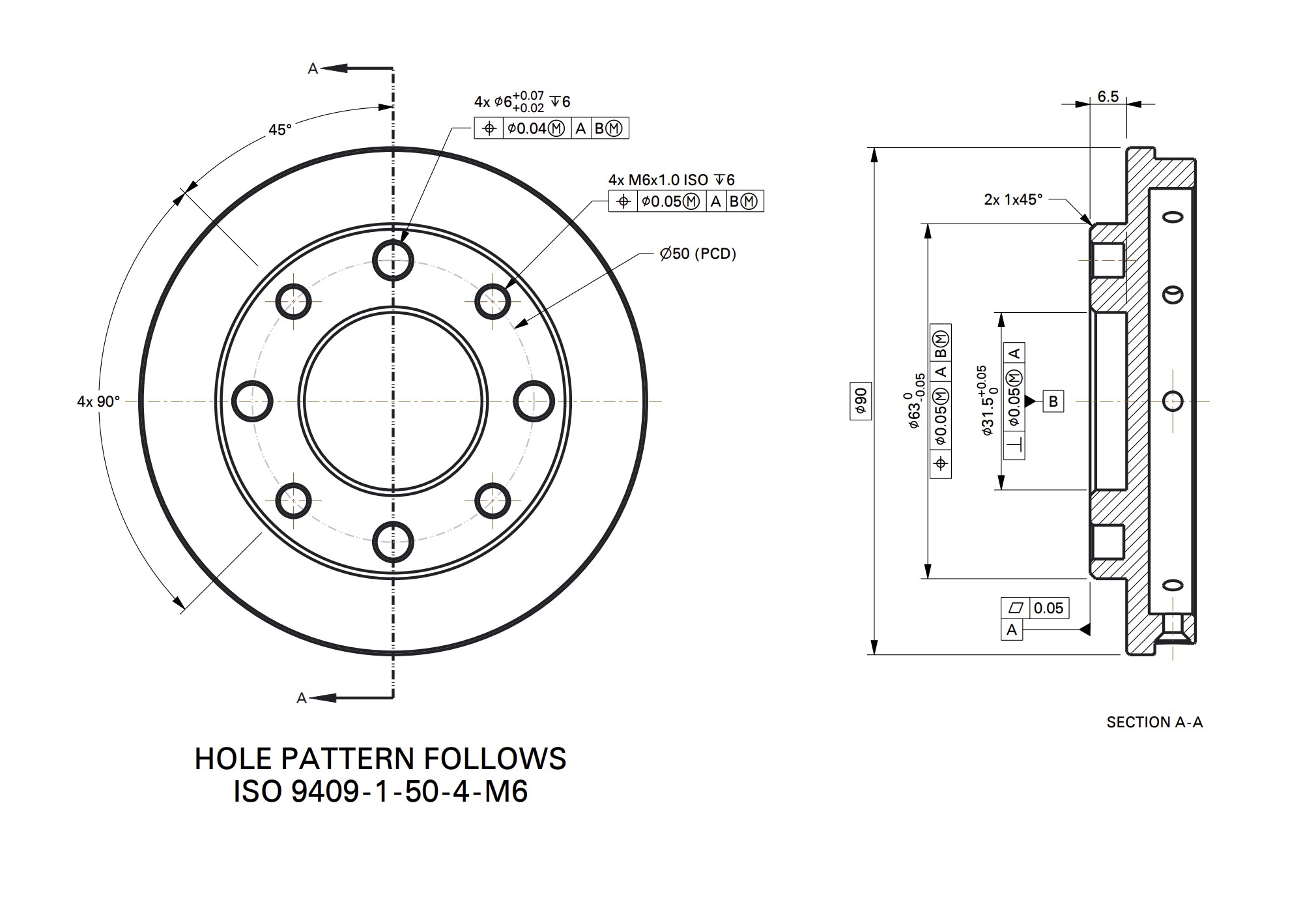
The Core robot uses the standard ISO 9409-1-50-4-M6 robot flange pattern. The pattern has 4 M6 bolts on a 50mm circle. Any tool that follows the standard ISO 50mm pattern will mount to the Core robot flange.
3.8.2 Fully Integrated Tools
Standard Bots supports full integration with the following tools. These tools can be fully controlled using standard instructions in the Standard Bots Routine Editor. Other tools can be controlled via digital I/O.
- OnRobot 2FG7 Parallel Tool
- OnRobot 2FG14 Parallel Tool
- OnRobot 3FG15 3 Finger Centric Tool
- OnRobot Dual Changer
- Schunk EGU
- Schunk EGK
Payload derating with EOATs. When operating with an end effector and payload together, the total combined mass must not exceed the payload limit listed in the Hardware Overview. At payloads above 16 kg, maximum robot speed is automatically reduced to 25% of the default speed settings (default tooltip speed: 0.75 m/s). This derating applies to all movements and is enforced once the payload mass is set in robot settings or within an Actuate Gripper step.
Follow the instructions provided with the tooling to connect the tooling to the robot flange, and connect the wire to the provided connector at the end of the robot arm.
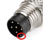
Be careful when attaching the M8 tool connector. Ensure that you line up the key with the receiver when you plug it in. Do not twist it, the pins are fragile and this can cause the pins to break.
Please ensure the robot is powered off when connecting tooling to the m8 port to reduce risk of any shorting during the connection process
3.8.3 Other Supported Tools
In addition to the above tools, Standard Bots generally supports most tools that mount to the 50mm flange and that support 24VDC discrete control. Please contact Standard Bots support for assistance with confirming tooling compatibility.
3.9 Control Box Inputs and Outputs
3.9.1 Digital Inputs and Outputs
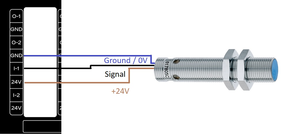
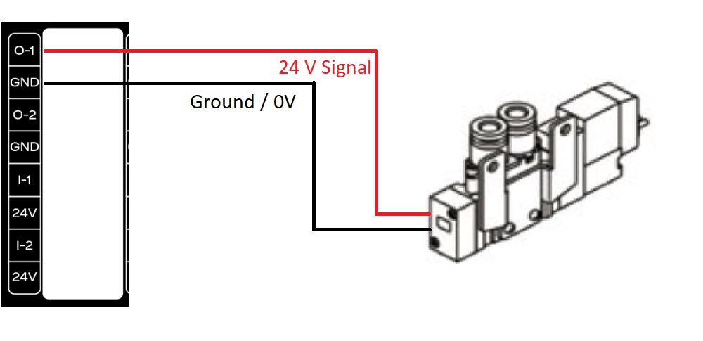
The Core control box supports 16 24VDC digital inputs and 16 24VDC digital outputs. The signals are sourcing or PNP. The digital outputs support up to 0.7 amps of output; for larger capacity use the digital outputs from the robot to drive a relay coil to a separate power source.
Example of wiring a proximity sensor into the Core control box:
Example of wiring a pneumatic valve into the Core control box:
3.9.2 I/O Power Select Feature
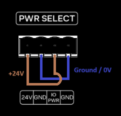
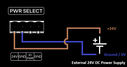
The Core control box enables users to manage input/output (I/O) functions using its integrated 24V power supply. Alternatively, an external 24V power supply can be used if preferred. The diagrams below illustrate both wiring configurations.
3.9.2.1 Integrated 24V Power Supply
The image below illustrates the wiring configuration for utilizing the integrated 24V power supply for I/O functionality.
3.9.2.2 External 24V Power Supply
The image below illustrates the wiring configuration for utilizing an external 24V power supply for I/O functionality.
3.10 Marvin Admin Page
The Marvin Admin page allows you to manage and access all of your robots in one location as well as giving you access to useful information. Please note that using the admin page is not necessary for using your robot.
To access the admin page, go to https://marvin.standardbots.com/ in your browser. There you should be able to enter your email address to access your organization’s page. If you are unable to enter your organization’s admin page, please reach out to Standard Bots Support.
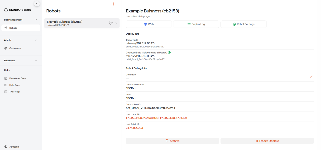
On the Bot Management tab you are able to access the list of robots that you own. Here you can access the robot through the web, see the robot’s installed software version and serial number, and here is where you can create a cloud, simulated, robot.
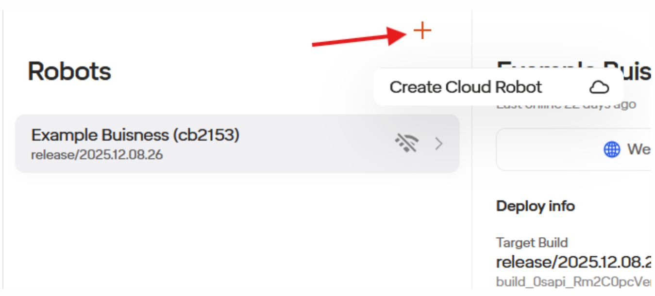
To make a cloud robot, select the orange plus sign at the top of the screen. There you will be able to give the cloud robot a name (which will be used to access your simulated robot on your browser by going to CloudRobotsName.sb.app) and the region. Afterwards you can hit Create. Please note that it does take multiple minutes for the cloud robot to be made. If you experience any issues, please reach out to support.
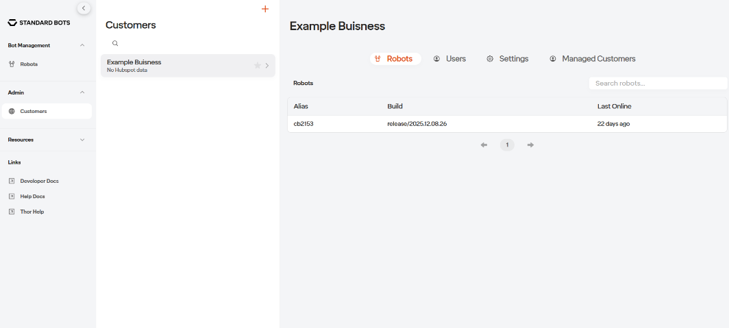
In the Admin Tab you will be able to access your organizations users and robots. Here you can add employees emails to the User’s list which will give them access to your Marvin Admin page. You can also manage your customer’s robots here if applicable.
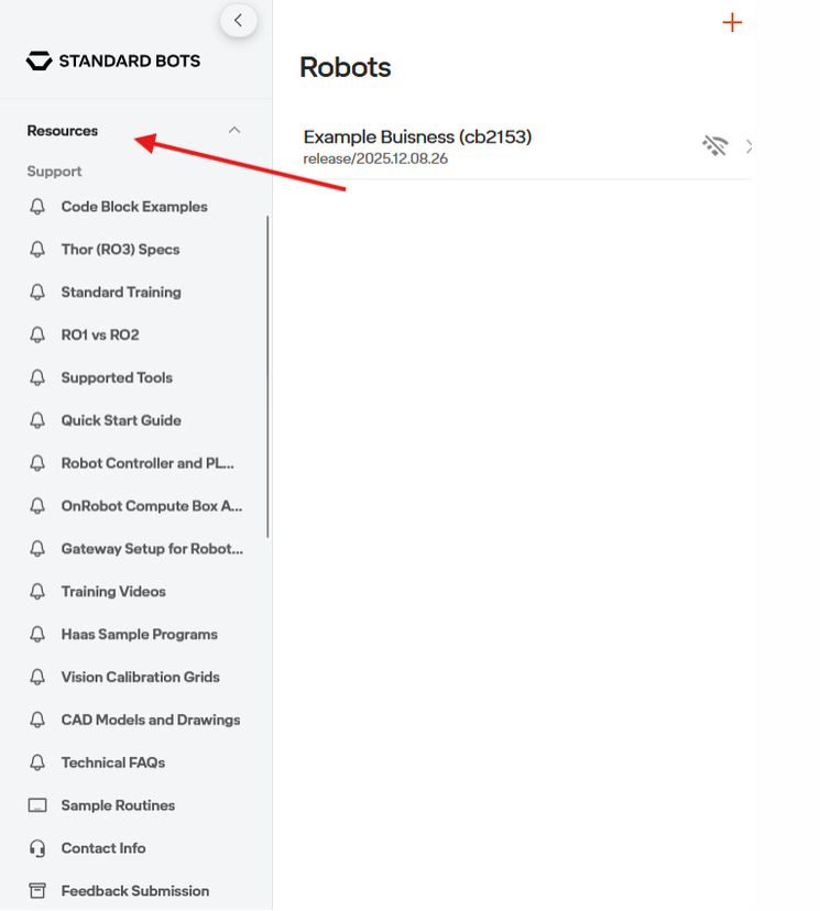
Next is the Resources Tab. Here you have access to useful information such as CAD files, example routines, supported tools, and much more.