4 Safety
4.1 Overview of Safety Features
The Core robot includes many safety features for operating in either collaborative or industrial applications. The exact implementation of these features will depend upon the application and risk assessment. The final performance level of the system will depend on the integration and must be calculated by the integrator.
Core has parameters for the below settings that can be fully customized for the end application and allow for integration with a wide variety of industrial safety components.
- Joint Collision Thresholds
- Joint Velocity, Acceleration, and Torque limits
- Emergency Stop Inputs
- Safety IO / OSSD
4.1.1 Emergency Stop
Pressing the E-Stop button on the front of the control box, or triggering any external E-Stop input, initiates a category-1 stop: power is cut to the arm motors after a controlled deceleration, and the brakes engage. The button latches mechanically — twist it clockwise to release before the robot can be re-armed.
External Emergency Stop devices can be wired into the control box’s safety inputs as redundant pairs. See Configuring Safety Inputs below for the input options and pairing requirements.
4.1.2 Response Time
Core responds to safety events within the tolerances in the below chart:
| Safety Input Event | Worst Case Detection Time | Worst Case Power Off Time | Worst Case Response Time |
|---|---|---|---|
| Internal Emergency Stop | 50ms | 600ms | 600ms |
| External Emergency Stop | 50ms | 600ms | 600ms |
| External Safety IO Slow Speed Input | 50ms | N/A | 600ms |
| External Safety IO Emergency Stop | 50ms | 600ms | 600ms |
| Tablet or Browser E-Stop | 1000ms* | 1600ms* | 1600ms* |
*Network Latency Dependent
| Safety Output Event | Worst Case Response Time |
|---|---|
| Robot E-Stop | 50ms |
4.1.3 Performance Level
The Core safety circuitry, including E-Stop circuitry and all digital inputs and outputs is PLe Cat 4.
4.2 Safety Settings
Safety Settings can be accessed by tapping the robot menu, then Settings > Safety.
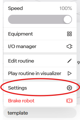
Settings are locked by default; click the “Unlock” button and re-enter the robot PIN to make the settings here editable.
Safety settings do not take effect until you tap “Apply Settings.”
4.2.1 Speed Limits
4.2.1.1 How Limits Work
Core has several levels of limits; the robot is always gated to the lowest of all of these:
- Global Limits: defined in Safety settings, which affect tooltip speed and the acceleration, velocity, and torque of joints.
- Speed Modifier % Slider: the robot can be slowed down on an as-needed basis (for instance, to trial a routine) without requiring access to Safety Settings.
- Step-Level Limits: the robot can also apply an alternate set of speed limits only for the duration of a specific step.
All of these settings are described below.
4.2.1.2 Editing Global Limits
The first tab of safety settings allows setting limits on the speed and acceleration of both the tooltip and the joints of the robot.
4.2.1.2.1 Using Factory Presets
By default, you will be presented with the choice of several presets.
The “default” (middle) setting restricts the robot to a tooltip speed of 0.75m/s, which is safe for most collaborative settings. Several others are available; if there are factors that may require more caution (such as the robot’s payload or end effectors), it may be desirable to select a more conservative setting.
Remember that many factors can affect whether a given speed is safe. Before putting the robot into production, you should always conduct a full safety assessment per ISO 10218-2 to determine the proper values for these settings and any other mitigations required.
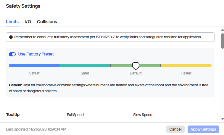
To review the values set for these factory presets, you can scroll down.
4.2.1.2.2 Custom Limits
To edit these limits, switch off “Use Factory Preset”; the limits should then become editable:
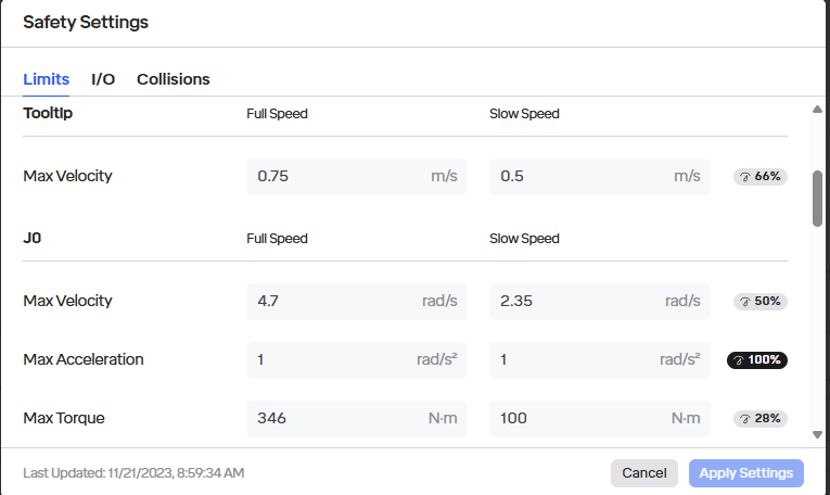
The following can be customized, both for when the robot operates at its full speed and in a “slow” mode that can be triggered via Safety I/O settings:
- Tooltip Speed: This limits the speed of the tooltip in Cartesian space.
- Per joint:
- Max velocity: This is the maximum angular change in the joint’s position per second permitted.
- Max acceleration: This affects the rate at which the joint can change speed. If this is too low, the robot may not be able to achieve the maximum velocity otherwise permitted during the course of a movement.
- Max torque: The maximum torque that the motor in the joint can exert.
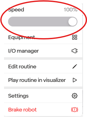
4.2.2 Speed Modifier % Slider
The robot can be slowed down from its maximum as needed inside the robot menu.
This is useful for trying out a routine before putting it into production.
Setting this slider only applies a cap to the maximum limits that would otherwise be set in Safety Settings; movements that were already slower than that are not affected.
4.2.3 Customizing Speed Limits For A Step
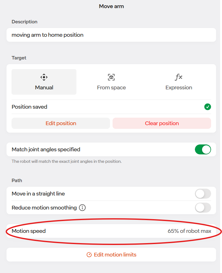
When editing a “Move” step, the “Motion Speed” shows the speed of this specific step. This is useful to notice for delicate movements or when required for safety. To change the speed, tap the “Edit Motion Limits” icon.
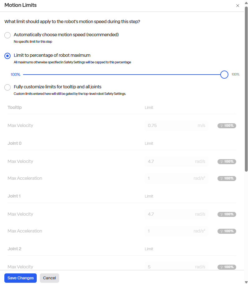
By tapping “Edit Motion Limits”, several options are available. The motion can be restricted to percentage of the maximum (as with the global speed modifier in the robot menu), or to a new set of custom limits.
Note that these limits apply whether the robot is operating at full speed or at any “slow” speed mode defined in safety settings. The robot will always apply the lowest of all limits in effect. It is also not possible to set torque limits on a per-step basis.
4.3 Safety I/O
In the safety Settings there are two tabs for I/O, Safety Inputs and Safety Outputs. Safety inputs allow you to tie in devices such as area scanners and key switches to discrete inputs onto your control box. Safety outputs allows the robot to indicate safety-critical elements of its status over discrete outputs to other devices like PLCs and other moving equipment that should stop when the robot does.
4.3.1 Configuring Safety Inputs
The sixteen 24V inputs on the control box are all safety-rated and can be used in pairs. Safety devices are connected in pairs to eliminate the possibility of a stray signal keeping the robot operating while actually in an unsafe condition. Therefore, if either of the paired inputs is below 24V, it will be treated as a “low” signal.
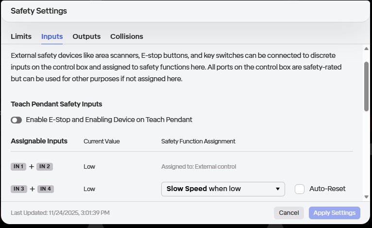
The following options are available:
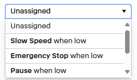
Safety Function Assignment: Any ports can be assigned to:
- Emergency Stop when low: Triggers a category-0 stop that brakes the robot and cuts power to arm.
- Pause when low or when high: Pauses the currently-running routine but does not brake the robot.
- Slow Speed when low: Makes the robot observe the “Slow Speed” set of limits defined in the “Limits” tab. This is useful, for instance, with an area scanner, to force the robot to move at a collaborative speed when people are nearby.
- Reset Safeguards When High: This will reset the effects of any safeguard that does not have auto-reset (see below). This has no effect on emergency stop.
Auto-Reset: This controls whether the effect of the function, once triggered, should go away (i.e. when we move back from low to high) or whether it requires a separate, explicit Reset. This is useful, for instance, with a sensor on a door to a fence around the robot: one would not want the robot to re-engage or speed up if the door is closed behind someone.
4.3.2 Configuring Safety Outputs
Additionally, the sixteen outputs on the control box are all safety-rated and are also used in pairs to eliminate the possibility of a stray signal keeping the robot operating while actually in an unsafe condition.
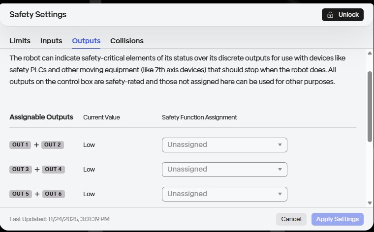
The following options are available:
- Emergency Stop
- Reduced Speed mode
- Full Speed mode
- Robot is moving
- Robot is still
4.3.3 Redundant-Pair Wiring Topology
The Core control box employs a redundant-pair wiring architecture for both safety inputs and outputs to meet PLe Cat 4 performance requirements. This topology ensures that a single stray signal or wiring fault cannot inadvertently create or mask a safety condition.
Input pairing. All 16 safety inputs on the control box are configured in eight pairs. When assigning a safety function to an input:
- Both inputs in a pair must be assigned to the same function (e.g. Emergency Stop, Pause, Slow Speed).
- A function is considered active only when both inputs in the pair are in the same state simultaneously.
- If one input differs from its pair (e.g. one high while the other is low), the system treats this as a wiring fault.
Output pairing. All 16 safety outputs are similarly paired. Both outputs in a pair mirror the same state, so external monitoring equipment (e.g. a PLC) can cross-check the pair to detect single-point faults in wiring or the control box and trigger a safe shutdown.
Example: E-Stop input wiring. To implement an external E-Stop button:
- Connect one terminal of the button to one input of a pair (e.g. DI-1).
- Connect the other terminal to the second input of the same pair (e.g. DI-2).
- Configure both DI-1 and DI-2 to “Emergency Stop when low” in Safety Settings.
- When the button is pressed, both inputs go low simultaneously and the control box registers a valid E-Stop command. If a wire breaks on a single line, the pair diverges and the system flags the wiring fault rather than producing a false E-Stop.
The Safety Inputs and Safety Outputs UIs in the robot menu present the 16 ports organized as eight pairs; selecting a pair and assigning a function configures both ports automatically.
4.4 Collisions & Protective Stops
When the robot is running a routine and encounters a collision, it will stop. The routine can be re-started with the “Play” button in the top toolbar. Every time a collision occurs, it will also log the time and force measured, which can be reviewed in the Notification (bell) section.
Collisions are detected with two methods: 1) by monitoring the current coming out of the joint motor to measure torque and find discrepancies, 2) by monitoring an IMU (accelerometer) inside each joint.
4.4.1 Adjusting Collision Sensitivity
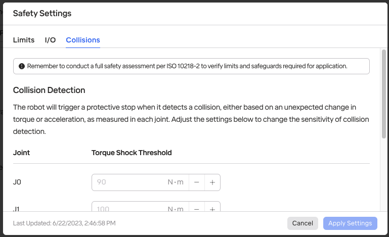
Depending on the environment and safety requirements, it may be desirable to change the sensitivity of collision detection. This can be done in the “Collisions” section of Safety Settings.
This allows adjusting the thresholds used for both methods: the torque shock threshold (in newton-meters) and the acceleration threshold used by the IMU (in m/s²).
4.5 Implementing a Safety Scanner
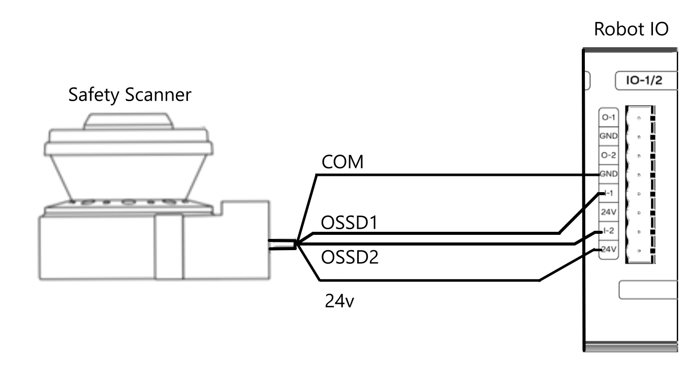
It is highly recommended that a safety scanner is used with the Core robot. Safety scanners, when implemented correctly, can slow or stop the robot automatically. This allows for operators to work safely around the robot.
Every safety scanner has a unique implementation method. Please consult the manufacturer’s guide for an in-depth procedure on how to install the device. Below is a generic wiring diagram intended to aid with installing a safety scanner.